Novel mechanical blood pressure meter movement

A sphygmomanometer, a mechanical technology, applied in vascular evaluation, cardiac catheterization, etc., can solve the problems of low displacement-rotation conversion efficiency, no dustproof performance, complicated movement assembly, etc., achieving ingenious overall structural design and reducing failures source, the effect of reducing the number of processing steps

Active Publication Date: 2015-12-16
HONSUN NANTONG
View PDF10 Cites 0 Cited by
  • Summary
  • Abstract
  • Description
  • Claims
  • Application Information

AI Technical Summary

Problems solved by technology

[0004] The movement installed in the watch case is the core component of the mechanical blood pressure gauge. The movement converts the mechanical displacement generated by the bellows into the mechanical rotation of the gear shaft. The traditional movements all use metal parts, and the processing technology of metal parts There are many, and the shape of parts is limited by the processing technology, resulting in a large number of parts, low production efficiency, high manufacturing cost, low displacement-rotation conversion efficiency, complex assembly of the movement, and the open movement does not have dustproof performance and other insurmountable obstacles. Therefore, There is an urgent need for a new technical solution to solve this technical problem

Method used


Image

  • Novel mechanical blood pressure meter movement
  • Novel mechanical blood pressure meter movement
  • Novel mechanical blood pressure meter movement

Examples


Embodiment 1

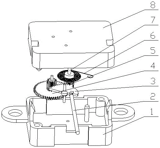
[0024] see figure 1 , a new type of mechanical sphygmomanometer movement, the sphygmomanometer movement is composed of a lower box cover 1, a thimble 2, a gear assembly, a pointer shaft 6, a torsion spring 7, and an upper box cover 8, and the thimble 2 is arranged on On the gear assembly, the torsion spring 7 is sleeved on the pointer shaft, and the gear assembly is arranged between the upper box cover and the lower box cover, and the upper box cover and the lower box cover are fixed together by a buckle structure. The gear assembly includes a sector gear 3, a double gear 4, and a pinion 5. The sector gear 3 meshes with the pinion end of the double gear 4, the large gear end of the double gear 4 meshes with the pinion 5, and the pinion 5 and The pointer shaft 6 is tightly press-fitted. In this technical solution, plastic gear transmission is used for the first time, and the plastic gear transmission has two-stage gear transmission, that is, the sector gear 3 meshes with the p...

Embodiment 2

[0026] see figure 1 , Figure 4 , as an improvement of the present invention, one end of the thimble 2 is set as a spherical end, the spherical end of the thimble 2 and the sector gear 3 cooperate through a spherical pair 19 and are provided with buckles to prevent falling off, the other end of the thimble 2 It is in contact with the moving end of the capsule of the mechanical blood pressure gauge head. The rest of the structures and advantages are exactly the same as in Embodiment 1.

Embodiment 3

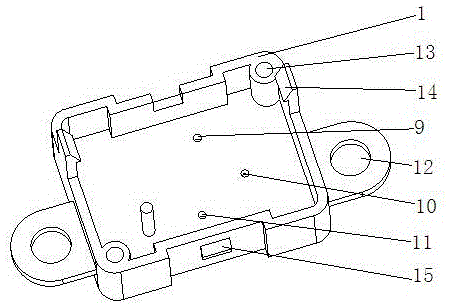
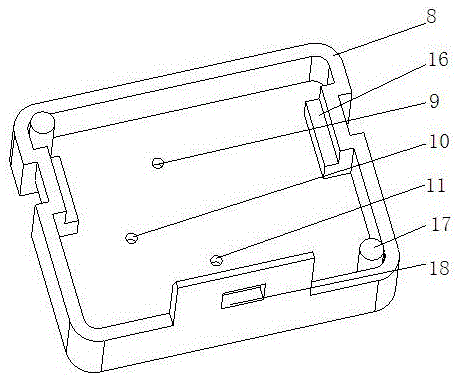
[0028] see figure 1 , image 3 , as an improvement of the present invention, the upper box cover 8 and the lower box cover 1 are provided with a sector gear shaft hole 9, a double gear shaft hole 10 and a pointer shaft hole 11, which are respectively used to install the sector gear 3 , duplex gear 4 and pinion 5. The rest of the structures and advantages are exactly the same as in Embodiment 1.


PUM


Abstract

The invention relates to a novel mechanical blood pressure meter movement. The movement is characterized in that the blood pressure meter movement is composed of a lower box cover, an ejector pin, a gear assembly, a pointer shaft, a torsion spring and an upper box cover. The ejector pin is arranged on the gear assembly, the pointer shaft is sleeved with the torsion spring, and the gear assembly is arranged between the upper box cover and the lower box cover which are fixed together through a buckle structure. According to the technical scheme, the overall structural design is ingenious, and the structure is compact and simple. Main parts of the movement are made of plastic good in forming performance. The mechanical blood pressure meter movement is optimized through the brand new design suitable for characteristics of the plastic parts, production efficiency is greatly improved, and performance is more stable.

Description

technical field [0001] The invention relates to a sphygmomanometer movement, in particular to a novel mechanical sphygmomanometer movement, which belongs to the technical field of medical equipment. Background technique [0002] With the development of economy and social progress, people's awareness of health and self-care has been continuously improved, and people's requirements for living environment, personal health care, medical treatment, etc. are getting higher and higher. Sphygmomanometer is a kind of indirect measurement method. The mechanical sphygmomanometer is convenient and quick to use, and is widely used day by day. [0003] Mechanical sphygmomanometer is a medical device used with stethoscope to measure human blood pressure. It consists of movement, bellows, dial, pointer and case. Among them, the diaphragm box converts the gas pressure to be measured into mechanical displacement, and the movement converts the mechanical displacement generated by the diaphrag...

Claims


Application Information

Patent Timeline
Patent Type & Authority Applications(China)
IPC IPC(8): A61B5/021
Inventor 李名尧贾振宁项国强
Owner HONSUN NANTONG
Why Eureka
Try Eureka