
Eureka
For R&D, Eureka makes reading and utilizing patents & technical documents easy.
Eureka AIR
Designed for self-driven R&D workflows. Generate viable solutions, solve complex R&D challenges, empower your innovation with AI.

Eureka Materials
Designed for material experts only. Revolutionize your material R&D, from search, analyze, to developing new materials.

TechResearch
Generate reliable direction feasibility study reports for your R&D in just a few steps.

TechSeek
Discover and master advanced knowledge NOW. Basics, ideas, possibilities, all at once.

TechMind
As an expert in R&D Theories, TechMind can generates customized viable solutions instantly.

TechRisk
Analyze your overall solution with one click, know your potential R&D risks in advance.

TechMonitor
Get weekly tech updates, stay abreast of the latest tech innovations and key insights.
A temperature-controlled metal casting method
A metal casting and metal technology, applied in the field of temperature-controlled metal casting, can solve the problems of uneven grain size, non-dense internal structure of castings, high energy consumption, etc., and achieve high production efficiency, compact internal structure, and uniform grain size Effect
- Summary
- Abstract
- Description
- Claims
- Application Information
AI Technical Summary
Problems solved by technology
Method used
Image

Examples
Embodiment 1
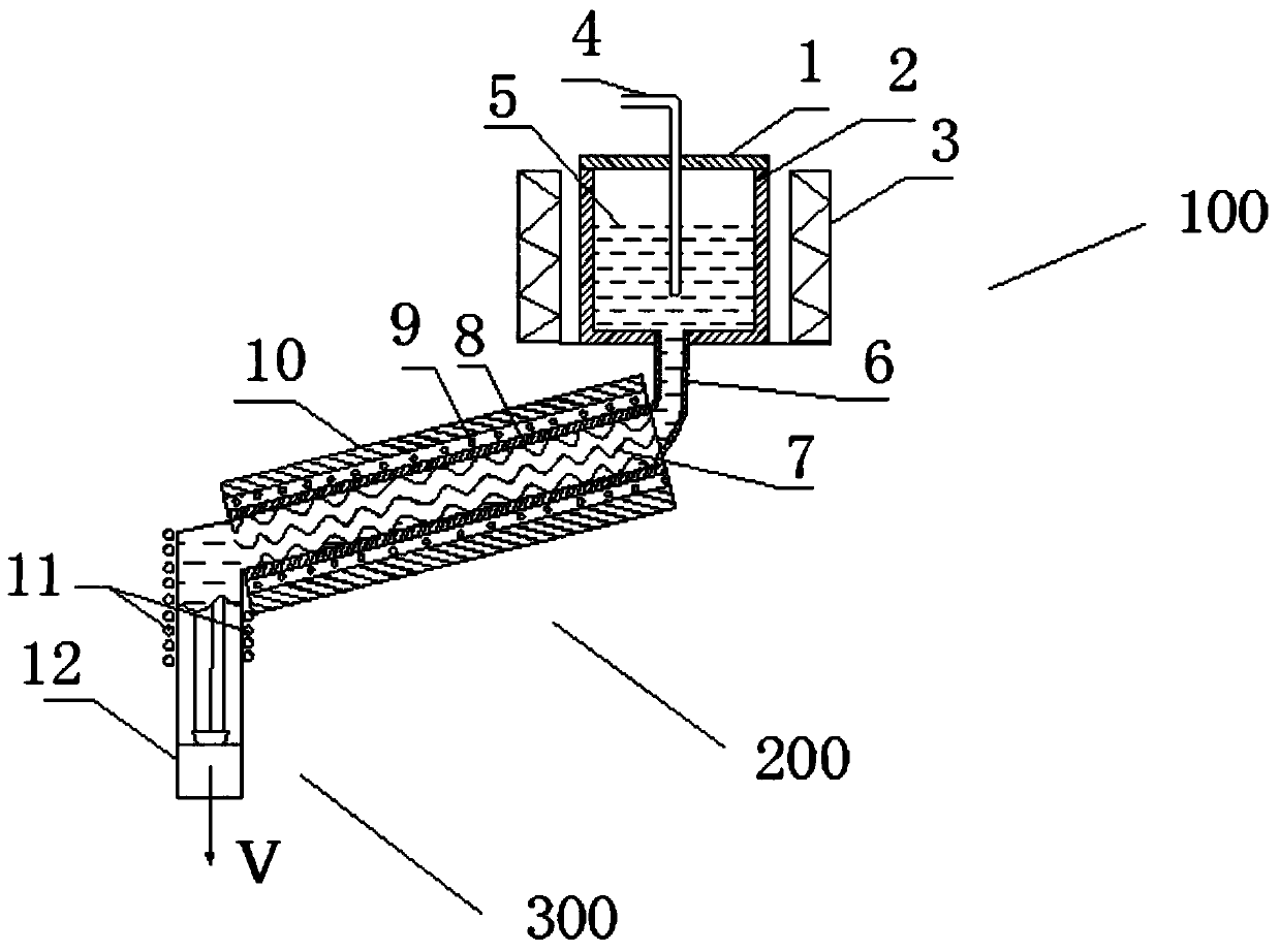
[0058] Such as figure 1 As shown, a temperature-controlled metal casting device includes a material holding device 100, a homogenizing device 200, and a stretching device 300; wherein, the material holding device 100 includes a crucible 1, a crucible top cover 2, an electromagnetic stirrer 3, and a flow guide Pipe 6; Homogenizing device 200 includes spiral pipeline 7, inner insulation layer 8, cooling pipe 9, outer insulation layer 10; Stretching device 200 includes heating device 11 and traction mechanism 12; Electromagnetic stirrer 3 wraps around the feeding device . In addition, the connection relationship between the material holding device 100, the homogenizing device 200, and the stretching device 300 is: the upper end of the homogenizing device 200 is connected to the draft tube 6 below the material holding device 100, and the stretching device 300 is connected to the lower end of the homogenizing device 200 .
[0059] The material holding device 100 of the above-ment...
Embodiment 2
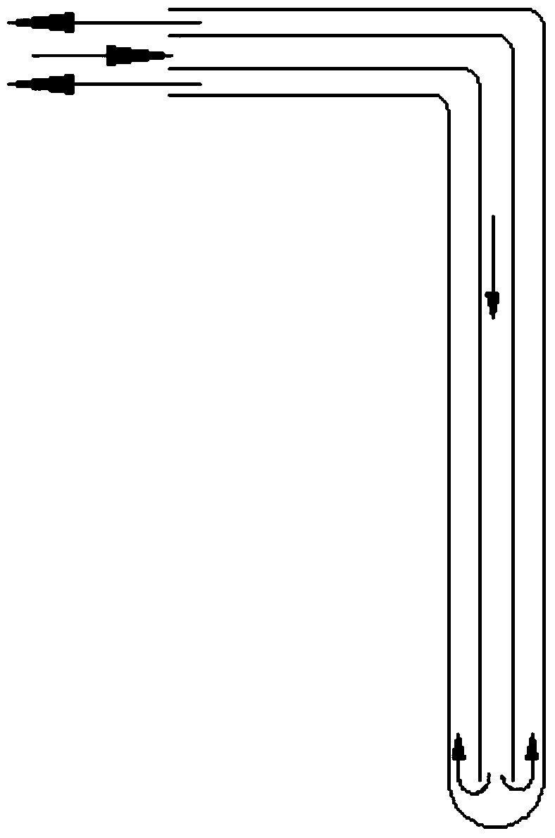
[0064] Can refer to Figure 1-3 The apparatus diagram, a kind of temperature control type metal casting method, comprises the following steps:
[0065] Step 1: Stir the molten metal 5 in the crucible 2 to achieve uniform composition mixing and uniform temperature distribution; conduct heat from the center of the crucible 2 in time through the heat conducting rod 4 at the center of the crucible 2;
[0066] Step 2: Flow the molten metal 5 in the crucible 2 into the homogenization device 200 through the draft tube 6;
[0067] Step 3: through the action of the spiral pipe 7 of the homogenization device 200, the metal solution 5 is formed into a homogenized turbulent flow, and under the action of the cooling pipe 9, the temperature of the metal at the outlet of the homogenization device 200 is reduced to below the solidus line;
[0068] Step 4: Control the temperature of the pre-stretched metal through the heating device 11 on the upper part of the traction mechanism 12; under the...
PUM
 Abstract
Description
Claims
Application Information
 - R&D Engineer
- R&D Manager
- IP Professional
- Industry Leading Data Capabilities
- Powerful AI technology
- Patent DNA Extraction
Browse by: Latest US Patents, China's latest patents, Technical Efficacy Thesaurus, Application Domain, Technology Topic, Popular Technical Reports.
© 2024 PatSnap. All rights reserved.Legal|Privacy policy|Modern Slavery Act Transparency Statement|Sitemap|About US| Contact US: help@patsnap.com