Laying-off, tube ending and tube bending integrated equipment

A technology for pipe bending and equipment, applied in the field of integrated equipment for blanking, pipe end and pipe bending, can solve the problems of high processing cost, low processing efficiency, high labor intensity, etc., to improve the processing range, ensure processing quality, and improve processing. The effect of precision

Active Publication Date: 2015-12-16
浙江长兴和良智能装备有限公司
View PDF4 Cites 39 Cited by
  • Summary
  • Abstract
  • Description
  • Claims
  • Application Information

AI Technical Summary

Problems solved by technology

[0003] The processing steps of the pipeline include blanking, pipe end, reaming, drilling and pipe bending, etc. In the prior art, the processing of each process of the pipeline is obtained by processing the corresponding equipment respectively, such as the long pipe needs to be processed by the blanking process. The traditional processing is generally carried out by manual cutting or mechanical cutting. Among them, manual cutting is gradually replaced by pipe cutting machines due to poor cutting accuracy, high labor intensity and low efficiency. The existing pipe cutting machines have a general structure. Both include a frame, a mandrel set on the frame, a pipe fitting clamping synchronous rotation mechanism, and a plurality of tool holders correspondingly arranged on the side of the mandrel disk, the pipe fittings are set on the mandrel, and the pipe fittings are clamped and synchronized. The rotating mechanism c...

Method used


Image

  • Laying-off, tube ending and tube bending integrated equipment
  • Laying-off, tube ending and tube bending integrated equipment
  • Laying-off, tube ending and tube bending integrated equipment

Examples


Embodiment Construction

[0038] In order to make the purpose, technical solutions and advantages of the embodiments of the present invention more clear, the following will clearly and completely describe the technical solutions of the embodiments of the present invention in conjunction with the drawings of the embodiments of the present invention. Apparently, the described embodiments are some, not all, embodiments of the present invention. Based on the described embodiments of the present invention, all other embodiments obtained by persons of ordinary skill in the art without creative efforts shall fall within the protection scope of the present invention.

[0039] In describing the present invention, it should be understood that the terms "center", "longitudinal", "transverse", "length", "width", "thickness", "upper", "lower", "front", " Orientation or position indicated by "back", "left", "right", "vertical", "horizontal", "top", "bottom", "inner", "outer", "clockwise", "counterclockwise", etc. T...


PUM


Abstract

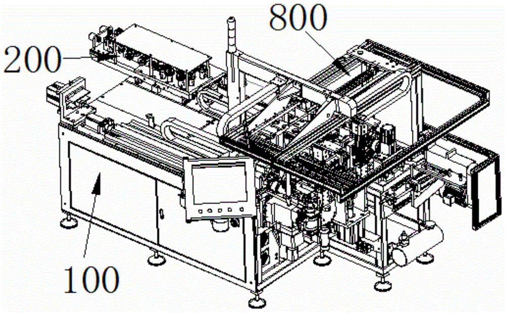
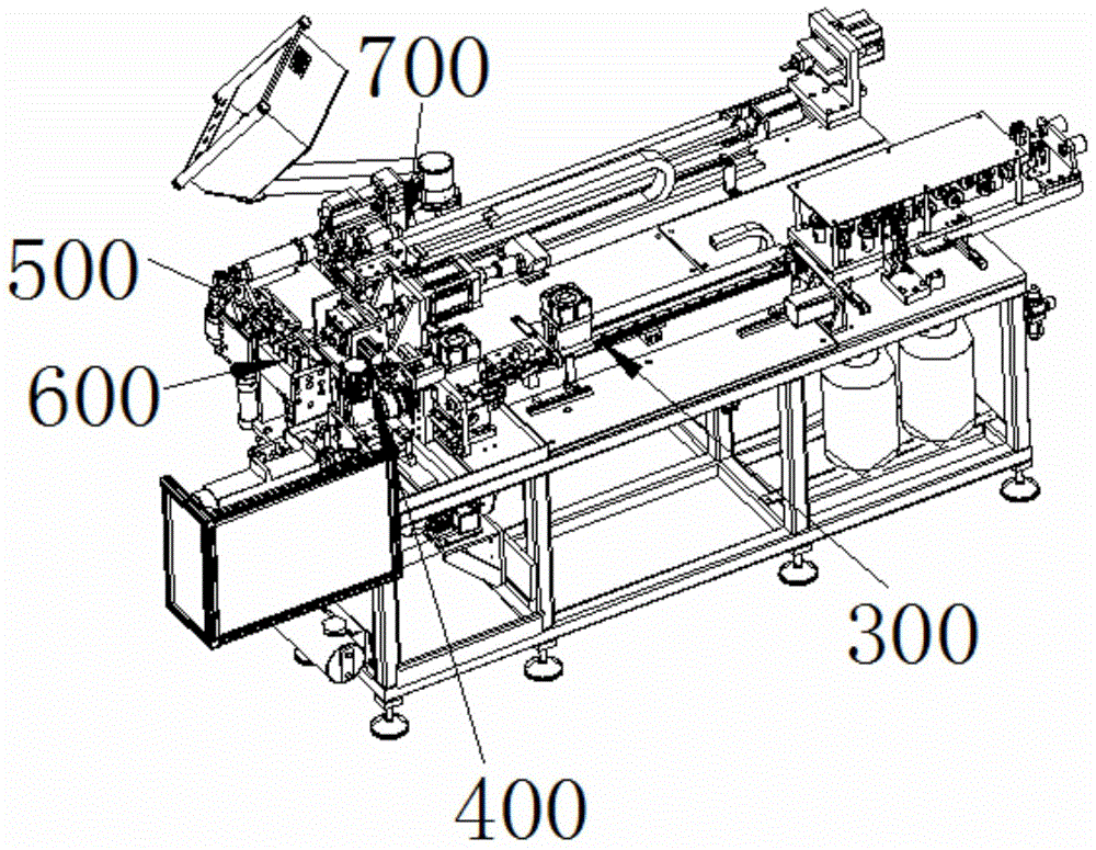
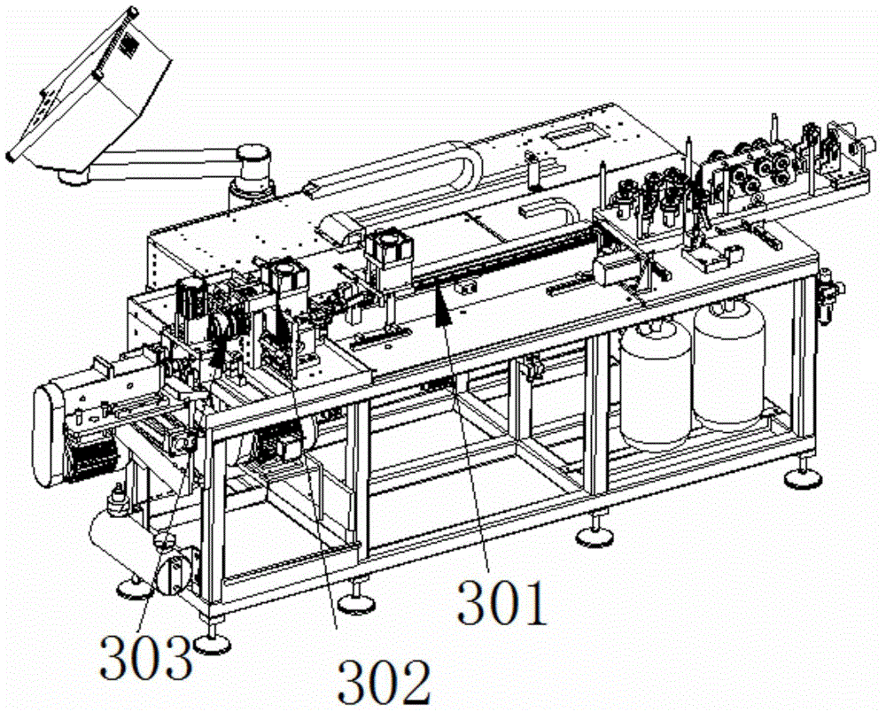
The invention discloses laying-off, tube ending and tube bending integrated equipment. The laying-off, tube ending and tube bending integrated equipment comprises a workbench. The laying-off, tube ending and tube bending integrated equipment further comprises a laying-off mechanism, a tube ending mechanism, a flaring/necking mechanism, a tube bending mechanism and a mechanical arm. The laying-off mechanism is used for conducting fixed-length laying-off on a workpiece and arranged on the workbench. The tube ending mechanism is used for conducting tube ending to the end portion of one end of the fixed-length workpiece and arranged in front of the laying-off mechanism in the advancing direction. The tube bending mechanism is used for bending the fixed-length workpiece. The flaring/necking mechanism is used for flaring or necking the end part of the other end of the fixed-length workpiece. The mechanical arm is used for assisting the conveying of the workpiece. The laying-off mechanism comprises a feeding device used for conducting fixed-length feeding and a cutting device used for conducting fixed-length cutting on the workpiece. The laying-off, tube ending and tube bending integrated equipment is simple in structure and suitable for processing of tubes with different sizes. Various processing such as cutting, laying-off, tube ending, hole shrinkage, hole chambering and tube bending can be conducted. The laying-off, tube ending and tube bending integrated equipment is suitable for assembly line production, and the processing efficiency and the processing precision are greatly improved.

Description

technical field [0001] The invention relates to the field of mechanical processing, in particular to an integrated equipment for blanking, pipe ends and pipe bending. Background technique [0002] In the path of transportation and connection, the pipeline is an indispensable connector. For example, in the pipeline transportation of liquid, gas and other media, the elbow is an indispensable connector to change the direction of the pipeline and facilitate transportation. [0003] The processing steps of the pipeline include blanking, pipe end, reaming, drilling and pipe bending, etc. In the prior art, the processing of each process of the pipeline is obtained by processing the corresponding equipment respectively, such as the long pipe needs to be processed by the blanking process. The traditional processing is generally carried out by manual cutting or mechanical cutting. Among them, manual cutting is gradually replaced by pipe cutting machines due to poor cutting accuracy, h...

Claims


Application Information

Patent Timeline
IPC IPC(8): B23P23/04
CPCB23P23/04
Inventor 李良有王元宾
Owner 浙江长兴和良智能装备有限公司
Why Eureka
Try Eureka