
Pinching-holding composite and adaptive robot finger device with rod and wheels connected in parallel

A robot finger, parallel technology, applied in the directions of manipulators, chucks, manufacturing tools, etc., can solve the problems of high manufacturing cost, small grasping range, lack of flexibility, etc., and achieves small motion dead zone, large grasping range, anthropomorphic effect

Inactive Publication Date: 2015-12-16
TSINGHUA UNIV
View PDF7 Cites 37 Cited by
  • Summary
  • Abstract
  • Description
  • Claims
  • Application Information

AI Technical Summary

Problems solved by technology

[0004] An existing double-joint co-direction transmission compound underactuated robot finger device, such as Chinese patent CN102161204B, can realize the function of coupling and rotating multiple joints first, and then adaptively grasping. The picking range is small; when grabbing an object, it is required that the object must be close to the base and the near-finger section initially, which reduces the grabbing efficiency; it is impossible to implement parallel pinching, and it is also impossible to grasp the object by opening outwards
Its disadvantages are that the grabbing range of the device is small, the multi-link mechanism is bulky, the appearance is not human, lack of flexibility, and the manufacturing cost is high

Method used


Image

  • Pinching-holding composite and adaptive robot finger device with rod and wheels connected in parallel
  • Pinching-holding composite and adaptive robot finger device with rod and wheels connected in parallel
  • Pinching-holding composite and adaptive robot finger device with rod and wheels connected in parallel

Examples


Embodiment Construction

[0036] The specific structure and working principle of the present invention will be further described in detail below in conjunction with the accompanying drawings and embodiments.

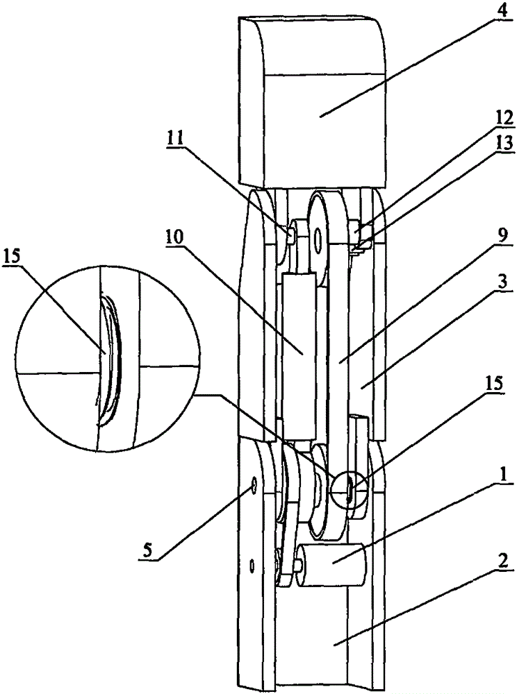
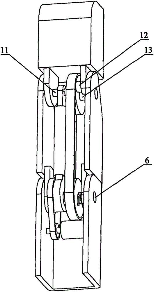
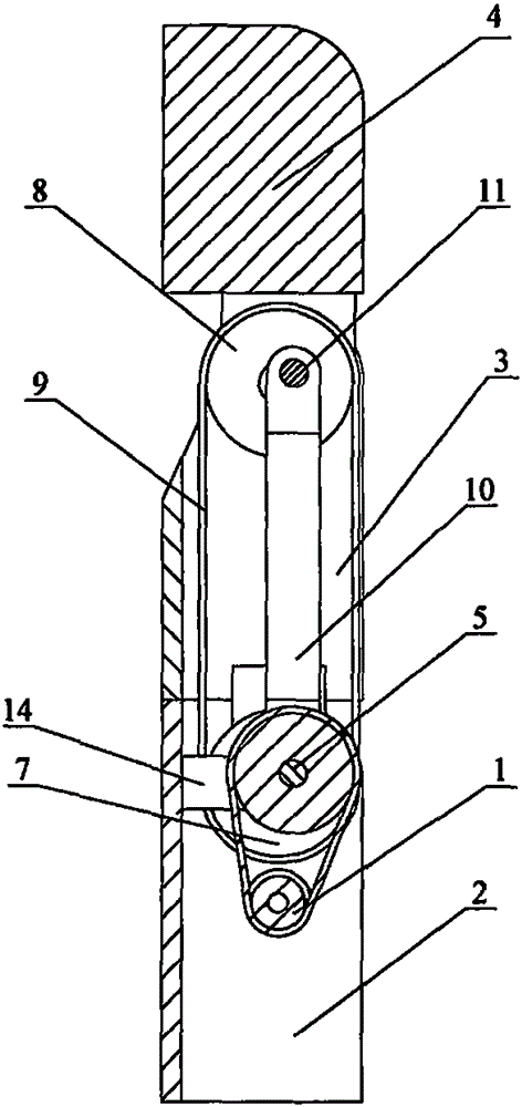
[0037] An embodiment of the rod-wheel parallel pinching compound self-adaptive robot finger device designed by the present invention, as figure 1 , figure 2 , image 3 , Figure 4 , Figure 5 , Image 6 , Figure 7 , Figure 8 with Figure 9As shown, it includes driver 1, base 2, first finger segment 3, second finger segment 4, first transmission wheel 7, second transmission wheel 8, transmission member 9, connecting rod 10, first shaft 5, second Shaft 6, third shaft 11, fourth shaft 12, fifth shaft 13, shift block 14 and spring member 15; the driver 1 is fixedly connected to the base 2, and the output shaft of the driver 1 is connected to the connecting rod 10; The first shaft 5 is sleeved in the base 2; the second shaft 6 is sleeved in the base 2; the first finger segment 3 is movably ...


PUM


Abstract

The invention belongs to the technical field of robot hands and discloses a pinching-holding composite and adaptive robot finger device with a rod and wheels connected in parallel. The robot finger device comprises a base, two finger sections, a driver, the two transmission wheels, transmission parts, the connecting rod, five shafts, a thumbing block and a spring part. The driver drives the connecting rod, and the two ends of the connecting rod are connected to the first shaft and the third shaft respectively in sleeved mode. The first shaft and the second shaft are arranged in the base in a sleeved mode. The third shaft is arranged in the second finger section in a sleeved mode. The fourth shaft is arranged on the second transmission wheel in a sleeving mode. The fifth shaft is arranged in the first finger section in a sleeved mode. The first finger section and the first transmission wheel are arranged on the second shaft in a sleeving mode. The second transmission wheel is arranged on the fifth shaft in a sleeving mode. The second finger section is connected to the fourth shaft in a sleeved mode. The robot finger device can grab articles in a pinching-holding composite and adaptive mode; the second finger section can be clenched to pinch the articles inwards or opened to pinch the articles outwards or hold the articles adaptively; the grabbing range is wide and the dead movement zone is small; the size is small, the appearance simulates the human, the flexibility is high, the structure is simple and reliable, and a sensing and controlling system is not needed.

Description

technical field [0001] The invention belongs to the technical field of robotic hands, and in particular relates to the structural design of a bar-wheel parallel pinch-grip compound self-adaptive robot finger device. Background technique [0002] As the end effector of the robot, the robot hand can be divided into two categories: anthropomorphic robot hand and general gripper. Anthropomorphic robotic hands are similar to human hands, and have the characteristics of multiple degrees of freedom, small size, and multiple grasping modes. Due to the high difficulty of controlling anthropomorphic robotic hands, a large number of sensing systems are required, the systems are expensive, and at the same time, they are not strong enough to be used in industrial production. Currently, it is mostly used in civilian robots, especially as prosthetics for the disabled. The universal gripper has low degrees of freedom, and each finger is usually controlled by one or two motors, so the syste...

Claims


Application Information

Patent Timeline
IPC IPC(8): B25J15/02B25J15/08
Inventor 梁达尧张文增陈强孙振国
Owner TSINGHUA UNIV
Learn More