Eureka AIR delivers breakthrough ideas for toughest innovation challenges, trusted by R&D personnel around the world.

A tire press machine

A technology of pressing machine and tires, which is applied in the directions of tire installation, tire parts, transportation and packaging, etc., can solve the problems of inconvenient adjustment, unreasonable force on the pressing claw, and low pressing quality when replacing large and small tire products. It is suitable for promotion and application, scientific structural design, and the effect of reducing the use of the site

Active Publication Date: 2017-11-28
SHIYAN HENGRUI MACHINERY EQUIP CO LTD
View PDF5 Cites 0 Cited by
  • Summary
  • Abstract
  • Description
  • Claims
  • Application Information

AI Technical Summary

Problems solved by technology

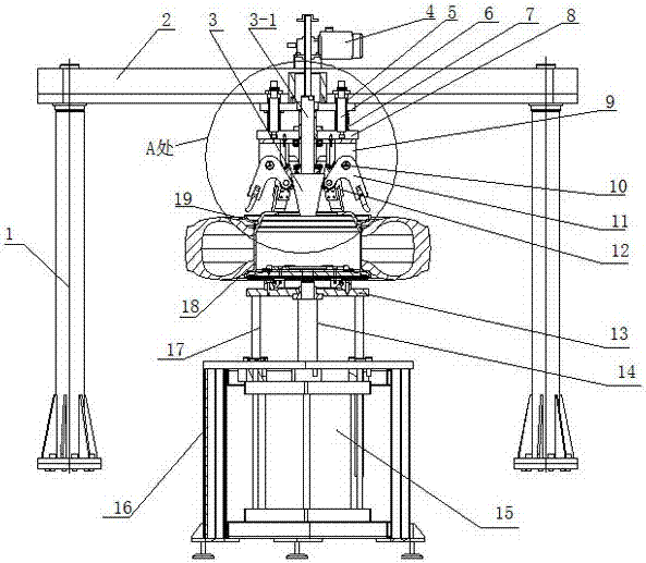
[0004] In order to solve the problems of low press-fit efficiency and low-quality press-fit quality of some products caused by unreasonable force on the pressure claws of existing tire press-fitting machines, inconvenient adjustment when changing tire products of different sizes, and certain hidden safety hazards, the present invention proposes a This kind of tire press-fitting machine can decompose the press-fitting force into reasonable outward and upward forces, no matter what kind of rim can be pressed into it smoothly, and the claws can be opened and adjusted easily, which can effectively improve the assembly efficiency and assembly of tires. quality, reduce labor intensity, strong versatility, and can effectively meet the large-volume, multi-frequency tire pressing work

Method used


Image

  • A tire press machine
  • A tire press machine
  • A tire press machine

Examples


Embodiment Construction

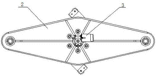
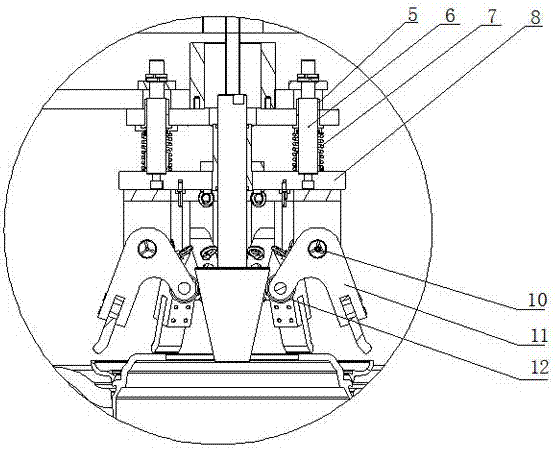
[0017] Such as figure 1 , figure 2 , image 3 As shown, the present invention is further described as follows: a tire press machine, including an upper frame 2, a lower frame 16, an electric control system (not expressed in the figure), the upper frame 2 is installed on the foundation through a column 1, and the lower frame The frame 12 is installed on the foundation, and the lower frame 16 is provided with a pneumatic jacking mechanism. The structure of the pneumatic jacking mechanism is that a lifting cylinder 15 is installed vertically upwards below the lower frame, and the positioning fixture 13 is located on the lower frame. On the top, the piston rod 14 of the lifting cylinder 15 is connected to the bottom of the positioning fixture 13, and the positioning fixture is vertically guided on the lower frame through a plurality of guide posts and guide sleeve assemblies 17;

[0018] The upper frame is equipped with a jaw press-fitting mechanism. The electric control system...


PUM


Abstract

The invention provides a tire press fitting machine. The tire press fitting machine comprises an upper rack and a lower rack; a pneumatic jacking mechanism is arranged on the lower rack, and a clamping jaw press fitting mechanism is correspondingly arranged on the upper rack; an electric control system controls the pneumatic jacking mechanism and the clamping jaw press fitting mechanism; the clamping jaw press fitting mechanism is composed of a clamping jaw floating mechanism and a clamping jaw opening mechanism; and according to a core structure of the clamping jaw opening mechanism, a plurality of clamping jaws are evenly distributed on a floating plate of a clamping jaw floating mechanism along the circumference; an electric pushing rod is arranged on the upper rack, and an opening cone body is connected to the output end of the electric pushing rod downwards; the inner ends of the clamping jaws are in contact with the opening cone body through rolling wheels, and the electric pushing rod drives the opening cone body to vertically move, so that adjustment of the opening magnitude of a plurality of pressing jaws is achieved. The tire press fitting machine is scientific and reasonable in structural design, easy and convenient to operate and capable of effectively improving the whole tire assembling efficiency; the quality of an assembled tire is correspondingly ensured, and the machine is also general for tires with the specifications ranging from 16 inches to 24 inches and with inner tubes.

Description

technical field [0001] The invention belongs to the automobile equipment manufacturing industry, in particular to a tire pressing machine. Background technique [0002] At present, the assembly of commercial vehicle tires mostly adopts the traditional manual paving method, or partly adopts the traditional old-fashioned tire press machine. The manual laying method means that a group of workers spread out on a field. After installing the tires and rims, they use hammers or tools to knock the retaining rings into the rims. It requires a lot of operators and is labor-intensive. It also makes people feel that the site is crowded. , The scene is chaotic; at the same time, through manual assembly, the operation process is quite cumbersome, the assembly efficiency is also low, and the product quality after assembly cannot be effectively guaranteed, so the scrap rate is high; moreover, due to the long-term and large-volume tire assembly work , It will also cause fatigue to the emplo...

Claims


Application Information

Patent Timeline
Patent Type & Authority Patents(China)
IPC IPC(8): B60C25/135
Inventor 柯昌清
Owner SHIYAN HENGRUI MACHINERY EQUIP CO LTD
Why Eureka
Eureka Blog
Learn More