
Fill interception and channeling system

An intercepting wall and intercepting net technology, applied in the field of sewage treatment, can solve the problems of increasing the moving speed of the filler, the area of ​​the intercepting net is large, and the operating cost is increased, and achieves the effect of improving the flow rate of the via hole, reducing the operating cost and saving materials.

Active Publication Date: 2018-01-09
大连宇都环境技术材料有限公司 +1
View PDF5 Cites 0 Cited by
  • Summary
  • Abstract
  • Description
  • Claims
  • Application Information

AI Technical Summary

Problems solved by technology

[0005] 3. In order to avoid the accumulation of the above-mentioned fillers, it is necessary to use a more powerful propeller to increase the moving speed of the fillers in the pool, resulting in serious wear between the fillers and the wall, and between the fillers and the paddles;
[0006] 4. The use of high-power submersible flowmakers has high energy consumption and increased operating costs;
[0008] 6. Due to the physical characteristics of the plate-type interception net, its bending and tensile strength is small and it is easy to deform. Therefore, when designing, it is necessary to use a smaller flow rate through the hole, so the area of ​​​​the interception net is larger and the cost is higher.
[0009] Therefore, the use of plate-type interception and dredging system has high energy consumption and poor reliability, which cannot meet the needs of MBBR treatment process

Method used


Image

  • Fill interception and channeling system
  • Fill interception and channeling system
  • Fill interception and channeling system

Examples


Embodiment Construction

[0021] The present invention will be further described below in conjunction with accompanying drawing.

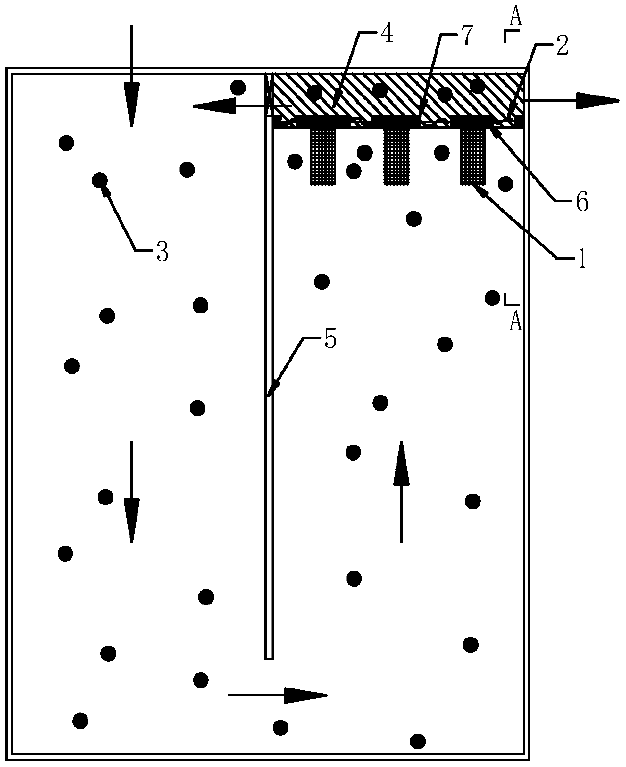
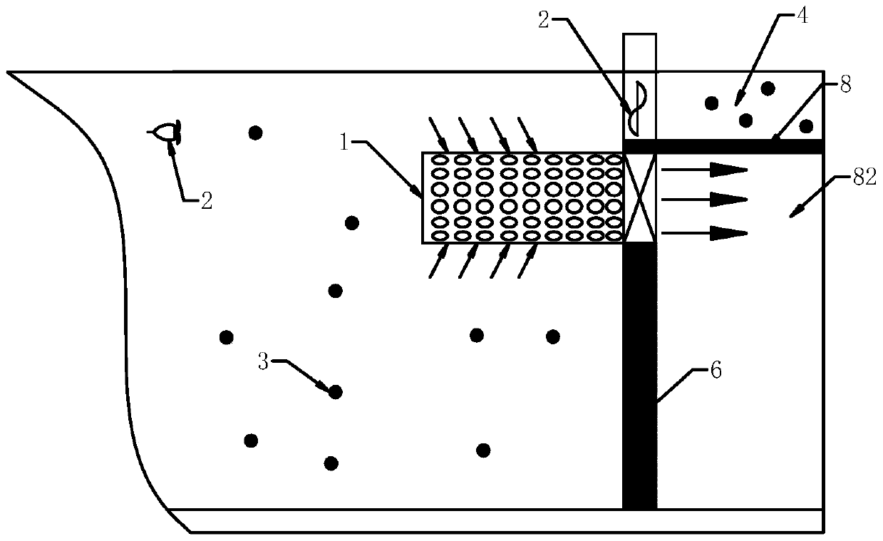
[0022] like figure 2 , image 3 As shown, the filler interception and dredging system of the present invention is provided with a diversion wall 5 along the length direction in the sewage treatment tank, the front end of the diversion wall 5 is attached to the front pool wall, and the rear end of the diversion wall 5 is connected to the rear pool. Keep the distance between the walls, the water inlet is arranged on one side of the front end of the diversion wall 5, and the water outlet is arranged on the other side of the front end of the diversion wall 5, the sewage enters the pool from the water inlet, bypasses the rear end of the diversion wall 5, and Turn around in the pool. In front of the water outlet, there is an interception wall 6 that is hard to the direction of the water flow. The middle part of the interception wall 6 is provided with a drainage hole, and the ...


PUM


Abstract

The invention discloses a filler interception and drainage system. A training wall is arranged in the length direction of a sewage treatment pool; the front end of the training wall is in fit with the pool wall; a gap is reserved between the rear end of the training wall and the pool wall; a water inlet is formed in one side of the training wall, and a water outlet is formed in the other side of the training wall; an interception wall is arranged in front of the water outlet; drain holes are formed in the middles of the interception wall; a cylindrical mesh covers each drain hole; a material discharge groove is formed in the upper end of the interception wall; a through-wall pump is mounted in the material discharge groove; the rear part of the interception wall is divided into an upper part and a lower part through a partition; the upper part is a filler platform; the through-wall pump pushes a filler and water to the filler platform; the lower part is a water draining cavity allowing sewage to enter, and then the sewage is discharged from the sewage treatment pool; a notch is formed in the training wall at the filler platform to enable the filler platform to be communicated with one end of the water inlet to form circulation inside the pool. The system combines the flow direction design, is reasonable in design, is free of partial blockage, saves materials, is low in cost, avoids accumulation at dead angles as the water flow is slow, and is low in running cost, thereby being suitable for filler drainage during sewage treatment.

Description

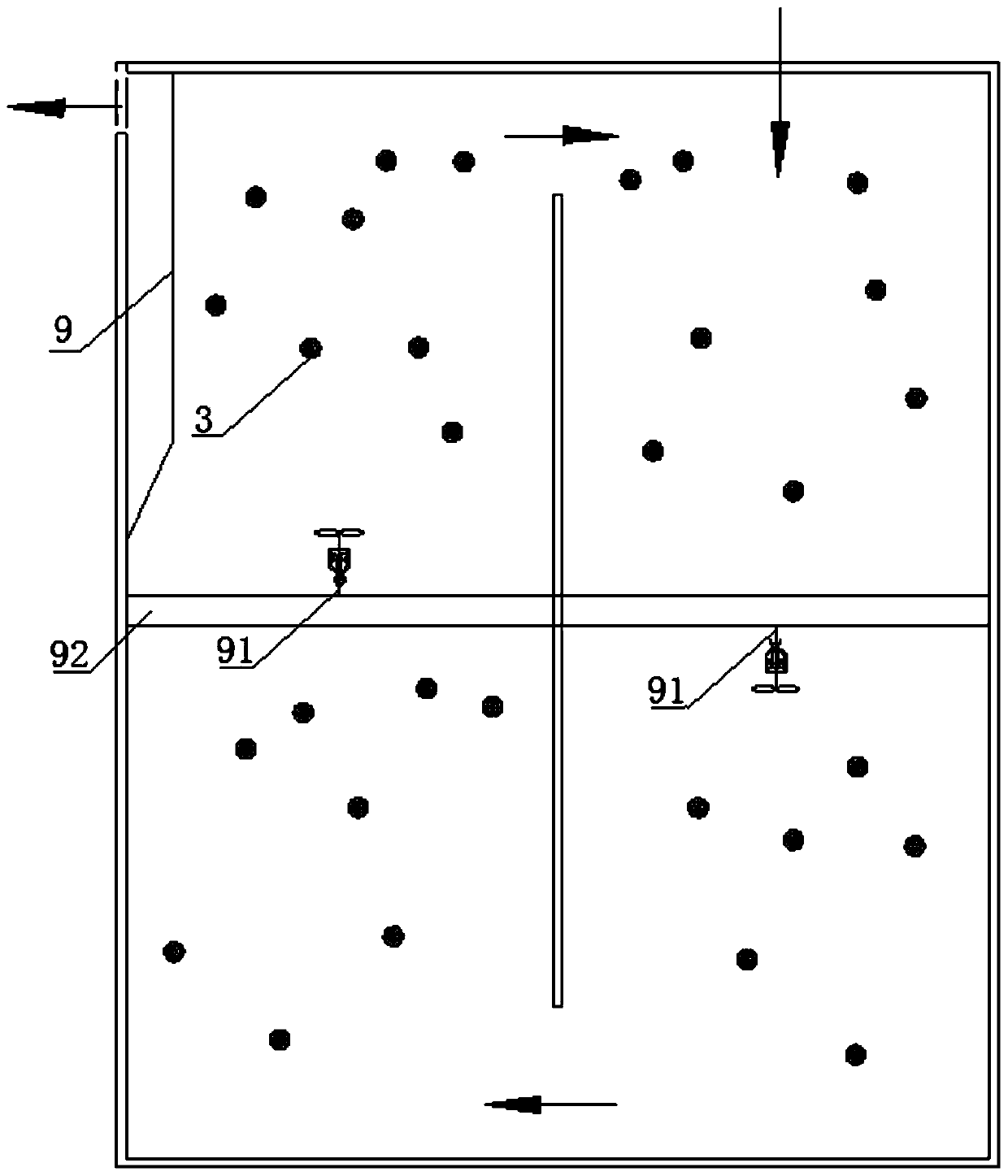
technical field [0001] The invention relates to the technical field of sewage treatment. Background technique [0002] For the MBBR process in the sewage treatment system, a certain proportion of biological suspension filler is placed in the water, and the biofilm is attached to the filler to purify the sewage. Sewage continues to flow into the pool from the water inlet, and flows along the guide in the pool for a period of time to be discharged from the water outlet. During this time, the sewage is decomposed and purified by the biofilm carrier on the filler, and the filler needs to be kept in the pool for circulation. In the prior art, in order to maintain the continuous inflow and outflow of sewage and the circulation of the filler, the filler interception and dredging system adopted such as figure 1 As shown, a diversion wall is set in the pool, and the front and rear ends of the diversion wall maintain a gap with the pool wall, and the sewage as a whole continues to ro...

Claims


Application Information

Patent Timeline
Patent Type & Authority Patents(China)
IPC IPC(8): C02F3/02
CPCY02W10/10
Inventor 权伍哲
Owner 大连宇都环境技术材料有限公司
Learn More