
Upward moving type movable formwork for continuous box girder construction

A mobile formwork and box girder construction technology, applied in bridges, bridge construction, erection/assembly of bridges, etc., can solve the problems of large one-time input materials, slow construction progress, poor overall stability, etc., to ensure structural stability and Safety, accelerated construction progress, and cost-saving effects

Inactive Publication Date: 2015-12-16
CCFEB CIVIL ENG
View PDF6 Cites 28 Cited by
  • Summary
  • Abstract
  • Description
  • Claims
  • Application Information

AI Technical Summary

Problems solved by technology

[0006] The invention provides an upward mobile formwork for continuous box girder construction to solve the problem that the existing ultra-wide continuous box girder construction method adopts the full hall support method, which has many construction procedures, large one-time input materials, and large space occupied by material stacking. , The construction cost is high, and the construction progress is slow; the technical problems of poor overall stability and high degree of danger due to the use of mobile formwork due to the overall horizontal opening of the mold

Method used


Image

  • Upward moving type movable formwork for continuous box girder construction
  • Upward moving type movable formwork for continuous box girder construction
  • Upward moving type movable formwork for continuous box girder construction

Examples


Embodiment Construction

[0027] The embodiments of the present invention will be described in detail below with reference to the accompanying drawings, but the present invention can be implemented in various ways defined and covered below.

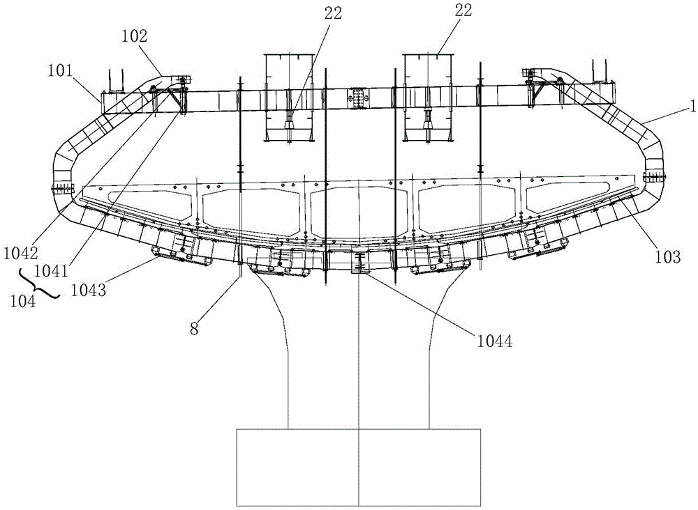
[0028] figure 1 It is one of the structural schematic diagrams of the upward mobile formwork used for continuous box girder construction in the preferred embodiment of the present invention; figure 2 It is the second structural diagram of the upward mobile formwork used for continuous box girder construction in the preferred embodiment of the present invention; image 3 It is a structural schematic diagram of the closed state of the hanging beam in the preferred embodiment of the present invention; Figure 4 It is a structural schematic diagram of the unfolded state of the hanging beam in the preferred embodiment of the present invention; Figure 5 It is a structural schematic diagram of the rear sliding beam of the preferred embodiment of the present invention...


PUM


Abstract

The invention discloses an upward moving type movable formwork for continuous box girder construction. The upward moving type movable formwork comprises a box girder body construction mold, a main beam, a nose beam and a rear sliding beam. The bottom of the box girder body construction mold is unfolded for box girder form removal or the bottom of the box girder body construction mold is closed so that a box girder can be poured. The main beam is supported on a middle supporting leg of the box girder and used for bearing the box girder body construction mold and driving the box girder body construction mold to move in the longitudinal direction of the box girder. The nose beam is supported on a front supporting leg of the box girder and used for guiding the main beam moving in the longitudinal direction of the box girder. The rear sliding beam is supported on the poured molded box girder and used for assisting the main beam in moving in the longitudinal direction of the box girder and being adjusted to be bent in the transverse direction of the box girder. The box girder body construction mold is suspended on the main beam, the nose beam is arranged at the advancing end of the main beam, and the rear sliding beam is arranged at the rear end of the main beam. Whole box girder pouring construction and mold movement are finished on the supporting legs and the poured molded box girder, the box girder body construction mold is opened from the bottom to form a folding span-crossing structure, and therefore the structural stability and safety of the whole formwork are guaranteed.

Description

technical field [0001] The invention relates to the field of bridge construction molds, in particular to an upward mobile formwork used for continuous box girder construction. Background technique [0002] At present, due to the traffic demand of major cities, ultra-wide multi-lane bridges are becoming more and more popular. [0003] At present, for the construction of ultra-wide continuous box girders, the full-wall support method is mostly used. The full house scaffolding method is a construction method in which scaffolding is erected densely at certain intervals to play a supporting role, and a large number of formwork supports are required during construction. The bracket method construction is to set up brackets at the bridge position, pour concrete for the bridge body on the brackets, and remove the formwork and brackets after the concrete reaches strength. The biggest advantage of the bracket method construction is that it does not require large-scale hoisting equip...

Claims


Application Information

Patent Timeline
IPC IPC(8): E01D21/00
Inventor 罗桂军彭云涌王小山肖洪波聂海柱李泽谈超张红卫
Owner CCFEB CIVIL ENG
Learn More