A method and device for measuring the moving speed of an object
A technology of moving speed and objects, applied in the computer field, can solve the problems of poor efficiency and high measurement cost, and achieve the effect of reducing measurement cost and improving measurement efficiency
- Summary
- Abstract
- Description
- Claims
- Application Information
AI Technical Summary
Problems solved by technology
Method used
Image
Examples
Embodiment 1
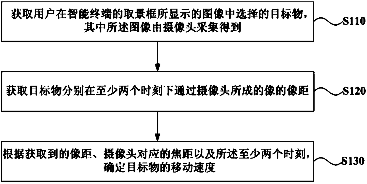
[0024] figure 1 It is a schematic flowchart of a method for measuring the moving speed of an object provided in Embodiment 1 of the present invention. The method can be performed by a device for measuring the moving speed of an object, the device is implemented by software and / or hardware, and can be integrated into an intelligent terminal such as a smart phone, a tablet computer or a personal digital assistant. see figure 1 The execution operations included in the method for measuring the moving speed of an object provided in this embodiment are specifically as follows.
[0025] S110. Obtain the target object selected by the user in the image displayed in the viewfinder frame of the smart terminal, where the image is collected by the camera.
[0026] Exemplarily, acquiring the target object selected by the user in the image displayed in the viewfinder frame of the smart terminal includes: detecting a touch gesture that the user acts on the image displayed in the viewfinder ...
Embodiment 2
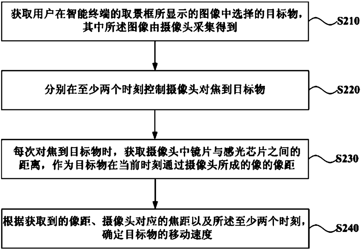
[0039] Figure 2A It is a schematic flowchart of a method for measuring the moving speed of an object provided by Embodiment 2 of the present invention. In this embodiment, on the basis of the first embodiment above, the operation of "obtaining the image distances of the images of the target object formed by the camera at at least two time points" is optimized. see Figure 2A The execution operations included in the method for measuring the moving speed of an object provided in this embodiment are specifically as follows.
[0040] S210. Obtain the target object selected by the user in the image displayed in the viewfinder frame of the smart terminal, where the image is collected by the camera.
[0041] S220. Control the camera to focus on the target at least two moments respectively.
[0042] S230. Acquire the distance between the lens in the camera and the photosensitive chip each time the target is focused on, and use it as the image distance of the image of the target fo...
Embodiment 3
[0059] image 3 It is a schematic structural diagram of a device for measuring the speed of an object provided by Embodiment 3 of the present invention. see image 3 , the specific structure of the device is as follows:
[0060] The target acquisition unit 310 is configured to acquire the target selected by the user in the image displayed in the viewfinder frame of the smart terminal, wherein the image is collected by the camera;
[0061] An image distance acquiring unit 320, configured to acquire the image distances of the images of the target object formed by the camera at at least two moments;
[0062] The moving speed determining unit 330 is configured to determine the moving speed of the target object according to the acquired image distance, the focal length corresponding to the camera, and the at least two moments.
[0063] Exemplary, the image distance acquisition unit 320 includes:
[0064] A focusing subunit 3201, configured to control the camera to focus on the ...
PUM
 Abstract
Description
Claims
Application Information
 - R&D
- Intellectual Property
- Life Sciences
- Materials
- Tech Scout
- Unparalleled Data Quality
- Higher Quality Content
- 60% Fewer Hallucinations
Browse by: Latest US Patents, China's latest patents, Technical Efficacy Thesaurus, Application Domain, Technology Topic, Popular Technical Reports.
© 2025 PatSnap. All rights reserved.Legal|Privacy policy|Modern Slavery Act Transparency Statement|Sitemap|About US| Contact US: help@patsnap.com


