Cell clamping mechanism and battery manufacturing apparatus

Active Publication Date: 2015-12-16
SHENZHEN CHENGJIE INTELLIGENT EQUIP CO LTD
View PDF4 Cites 2 Cited by
  • Summary
  • Abstract
  • Description
  • Claims
  • Application Information

AI Technical Summary

Problems solved by technology

Therefore, during the winding process of the battery core, the tightness between the materials of the battery core cannot be further improved, and the quality of the battery core cannot be further improved.
In addition, since the winding and clamping of the battery cells are carried out separately, the automated production of Ni-MH batteries is complicated

Method used


Image

  • Cell clamping mechanism and battery manufacturing apparatus
  • Cell clamping mechanism and battery manufacturing apparatus
  • Cell clamping mechanism and battery manufacturing apparatus

Examples


Embodiment Construction

[0028] In order to further explain the technical means and effects of the present invention to achieve the intended purpose of the invention, the specific implementation and structure of the battery clamping mechanism and battery manufacturing device proposed according to the present invention will be described below in conjunction with the accompanying drawings and preferred embodiments. , features and their functions are detailed as follows:

[0029] The aforementioned and other technical contents, features and effects of the present invention will be clearly presented in the following detailed description of preferred embodiments with reference to the drawings. Through the description of specific implementation methods, the technical means and effects of the present invention to achieve the intended purpose can be understood more deeply and specifically, but the attached drawings are only for reference and description, and are not used to explain the present invention limit...


PUM


Abstract

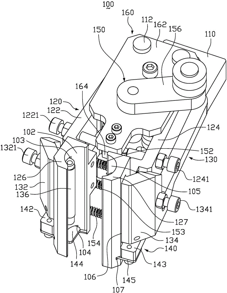
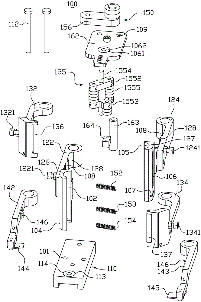
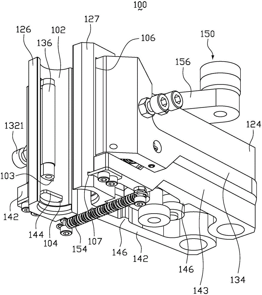
A cell clamping mechanism comprises a mounting base, a die clamp, a pinch roller clamp and a driving assembly; the die clamp and the pinch roller clamp are hinged on the mounting base through hinge pins; the die clamp comprises a first chuck and a first chuck which are arranged in opposite; a first clamping groove and a first movable hole which penetrates through the first clamping groove and is communicated with the first clamping groove are formed in the first chuck; a second clamping groove and a second movable hole which penetrates through the second clamping groove and is communicated with the second clamping groove are formed in the second chuck; the pinch roller clamp comprises a first pinch roller and a second pinch roller which are arranged in opposite; the first pinch roller passes through the first movable hole to be formed in the first clamping groove; the second pinch roller passes through the second movable hole to be formed in the second clamping groove; and the driving assembly is hinged on the mounting base and used for driving the first chuck and the second chuck to move close to each other or far from each other, and for driving the first pinch roller and the second pinch roller to move close to each other or far from each other. The cell clamping mechanism can improve the cell quality as well as improve the automatic production of batteries. The invention also relates to a battery manufacturing apparatus.

Description

technical field [0001] The invention relates to a battery production device, in particular to a battery cell clamping mechanism and a battery production device. Background technique [0002] As a kind of clean energy, Ni-MH battery has been widely used because of its light weight, long service life, no pollution to the environment and many other advantages. The main structure of the nickel-metal hydride battery includes a casing and a battery cell arranged in the casing (the battery core mainly includes positive and negative electrode sheets and a multi-layer separator wound to form). [0003] The production of Ni-MH batteries is mainly to use the winding mechanism to wind the cell material into a cylindrical cell structure, and then the mechanical arm clamps the wound-shaped cell and transfers the cell to the next Ni-MH battery. Battery manufacturing process (such as the process of putting the battery into the casing, etc.). The existing winding mechanism winds the cell a...

Claims


Application Information

Patent Timeline
IPC IPC(8): H01M10/28
CPCH01M10/286Y02E60/10Y02P70/50
Inventor 余劲平余传
Owner SHENZHEN CHENGJIE INTELLIGENT EQUIP CO LTD
Why Eureka
Try Eureka