Connector, contact member thereof and lock sleeve of contact member

A technology of contacting parts and locking sleeves, which is applied to the parts, connections, electrical components and other directions of the connecting device, can solve the problems of increased use cost, waste, and the locking sleeve cannot be removed from the optical fiber, etc., and achieves maintenance and replacement of the lock. The effect of tight sleeve is convenient, the use cost is reduced, and the separation is convenient

Active Publication Date: 2015-12-16
CHINA AVIATION OPTICAL-ELECTRICAL TECH CO LTD
View PDF8 Cites 1 Cited by
  • Summary
  • Abstract
  • Description
  • Claims
  • Application Information

AI Technical Summary

Problems solved by technology

However, this kind of connector is closed in the circumferential direction of the locking sleeve. When assembling, the optical fiber passes through the rear end of the locking sleeve and is fixedly connected to the pin positioning seat and the pin parts at the front end of the locking sleeve. After the assembly is completed, the locking sleeve cannot Removed from the optical fiber, once the locking key of the locking sleeve is damaged o...

Method used


Image

  • Connector, contact member thereof and lock sleeve of contact member
  • Connector, contact member thereof and lock sleeve of contact member
  • Connector, contact member thereof and lock sleeve of contact member

Examples


Embodiment 1

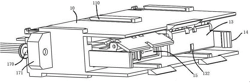
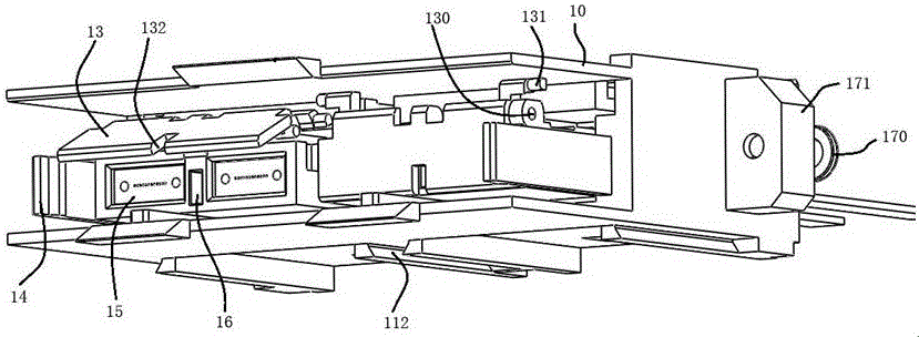
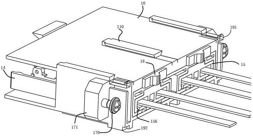
[0026] Embodiment 1 of the connector of the present invention: the connector in this embodiment is a socket connector, such as Figure 1-5 As shown, it includes a housing 10 and a contact member 15 arranged in the housing 10. The housing 10 is a rectangular housing, and two installation structures for installing the contact member 15 are arranged side by side inside the housing 10. The contact member 15 is installed on the Inside the housing 10 and extending in the front and rear directions; the left and right sides of the housing 10 are provided with a connecting structure for fixed connection with the socket connector mounting plate, the connecting structure includes connecting ears 171 and connecting screws 170 mounted on the connecting ears 171 , the rear side of the connecting ear 171 is used to fit the board surface of the socket connector mounting plate and is locked and fixed by the connecting screw 170; The position-limiting elastic hook 14 extends in the front-rear d...

Embodiment 2

[0031] Embodiment 2 of the connector of the present invention: the connector in this embodiment is a plug connector, such as Figure 6-9As shown, it includes a housing 20 and a contact member 25 arranged in the housing 20. The housing 20 is a rectangular housing, and four installation structures for installing the contact member 25 are arranged side by side inside the housing 20. The contact member 25 is installed on Inside the housing 20 and extending in the front and back directions; the left and right sides of the housing 20 are provided with floating connection structures for floating connection with the plug connector mounting plate. In this embodiment, the floating connection structures include The floating connecting ear 271 and the floating connecting piece used to connect the floating connecting ear 271 and the plug connector mounting plate. Wherein, the floating connection ear 271 is an ear plate that hangs outwards from the left and right side walls of the housing 2...

Embodiment 3

[0037] Embodiment 3 of the connector of the present invention: the difference from Embodiment 1 is that the lateral channel is arranged on the horizontal side wall and is a wave groove bent in the left and right directions.

[0038] Embodiment 4 of the connector of the present invention: the difference from Embodiment 1 is that the lateral channel is arranged on the vertical side wall and is a wave groove bent in the up and down direction, and the wave groove is arranged on the vertical side wall the middle position.

[0039] Embodiment 5 of the connector of the present invention: the difference from Embodiment 1 is that the locking sleeve is cylindrical with a central channel, and the outer peripheral surface of the cylindrical sleeve is provided with a lock with an adapter socket. The locking clips are tightly connected, and the side phase channel is an opening arranged on the circumferential direction of the cylindrical sleeve body.

[0040] The embodiment of the contact p...


PUM


Abstract

The invention provides a connector, a contact member thereof and a lock sleeve of the contact member. The connector comprises a shell and the contact member; the contact member is arranged in the shell and comprises the lock sleeve; the lock sleeve comprises a center channel through which a cable passes from front to back; and a lateral channel for enclosing and taking out the cable in a direction vertical to the axis of the center channel is formed in the lateral wall of the lock sleeve. The lateral channel for enclosing and taking out the cable in the direction vertical to the axis of the center channel is formed in the lateral wall of the lock sleeve of the connector provided by the invention, so that the cable in the center channel can be taken out through the lateral channel when the lock sleeve is damaged and needs to be replaced or repaired; separation of the lock sleeve and the cable is facilitated; the lock sleeve is relatively convenient to maintain and replace; the cable does not need to be cut off; the use cost is also reduced; and waste is avoided.

Description

technical field [0001] The invention relates to a connector, its contact parts and its locking sleeve. Background technique [0002] With the development of communication and information technology, fiber optic connectors are widely used in optical signal transmission systems. The Chinese invention patent with the authorized announcement number CN101447617B and the authorized announcement date of 2011.12.28 discloses a split connector, including a housing and a contact part arranged in the housing. The contact part includes the first housing, which is the pin positioning seat And the second housing is the locking sleeve, the pin positioning seat and the locking sleeve are assembled through the slot and the tongue, the pin positioning seat and the locking sleeve are respectively provided with channels for the optical fiber to pass through axially, and the optical fiber Insert from the rear side of the locking sleeve, pass through the front side of the pin positioning seat an...

Claims


Application Information

Patent Timeline
IPC IPC(8): H01R13/506
Inventor 刘卫锋崔艳磊周生贺孙亚磊
Owner CHINA AVIATION OPTICAL-ELECTRICAL TECH CO LTD
Why Eureka
Try Eureka