Bus connector

A technology of busbar connector and busbar, which is applied in the direction of connection, parts of connecting devices, contact parts, etc., can solve problems such as incomplete fit, complex structure, poor contact, etc., and achieve increased current carrying capacity, uniform electric field distribution, and resistance value Reduced effect

Inactive Publication Date: 2015-12-16
YIHE ELECTRIC GRP
View PDF6 Cites 0 Cited by
  • Summary
  • Abstract
  • Description
  • Claims
  • Application Information

AI Technical Summary

Problems solved by technology

[0002] At present, the existing commonly used busbar connectors use lap-joint or plug-in type to connect the contacts to the body of the bus-bar connector. Due to the complex structure of the lap-joint or plug-in busbar connectors, the resistance is large and more wires are required. materials, and the existing structure has problems of poor contact and incomplete fit, which affect the current-carrying

Method used


Image

  • Bus connector
  • Bus connector
  • Bus connector

Examples


Embodiment Construction

[0023] The present invention will be further described below in conjunction with the accompanying drawings and embodiments.

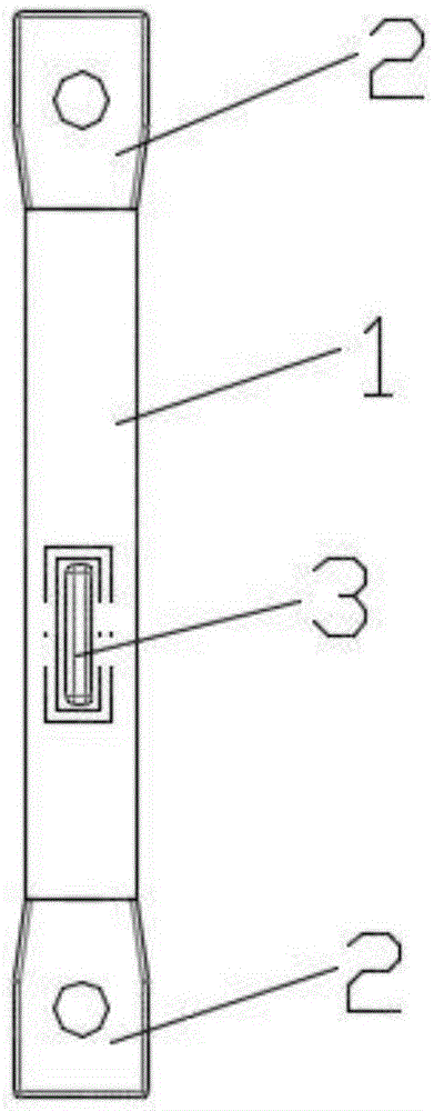
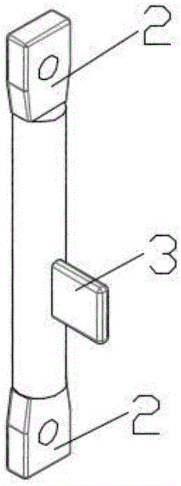
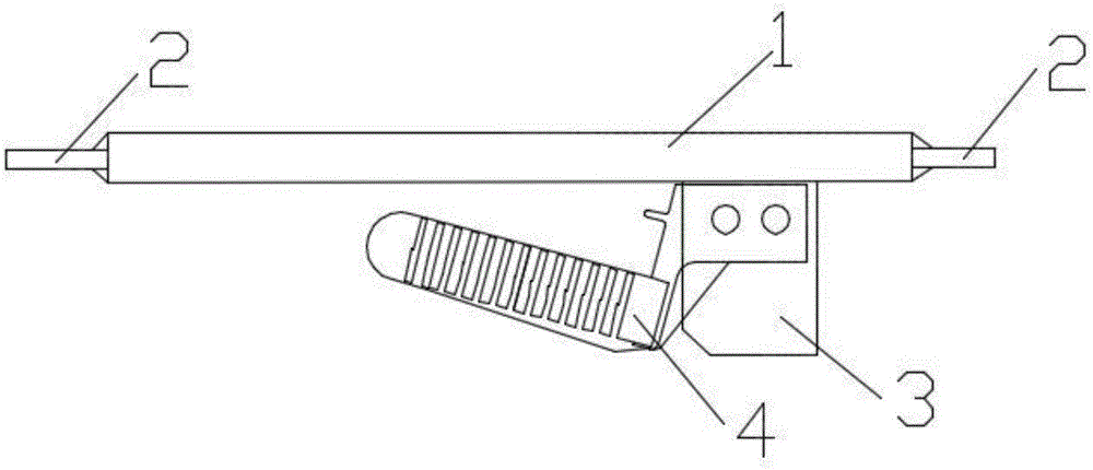
[0024] Such as figure 1 and figure 2 As shown, a busbar connector includes a busbar connector body 1 and a static contact 3 fixedly arranged on the surface of the busbar connector body 1. The ends of the busbar connector body 1 are respectively provided with sleeves connected to adjacent busbars. The terminal 2, the static contact 3 is connected to the movable contact of the isolating switch and the load switch, or overlapped with the arc extinguishing grid; the busbar connector body 1 and the static contact 3 are of an integrated structure.

[0025] The current flows through the terminal 2 of the busbar connector and flows into the other terminal of the busbar connector and the moving contact or the arc extinguishing grid connected to the moving contact of the isolating switch and the moving contact of the load switch respectively through the body of...


PUM


Abstract

The invention discloses a bus connector. The bus connector comprises a bus connector body and a static contact fixed on the surface of the bus connector body. End parts of the bus connector body are respectively provided with a wiring end connected with a sleeve of an adjacent bus. The static contact is in contact with a moving contact of an isolation switch and a moving contact of a load switch or is lapped with an arc extinguishing grid sheet. The bus connector body and the static contact form an integrated structure. The bus connector has the advantages that the static contact is fixedly arranged on the side surface of the bus connector body, so that the materials are saved, the resistance is lowered, and the materials are saved; the static contact is fixedly arranged on the bus connector body, so that the lapping area between the contact and the body is reduced, and the technology complexity is lowered; silver is plated on the surface of the static contact, so that mechanical running-in of the isolation or load switch is increased, and the usage time is prolonged; the current-carrying capacity is improved; and the distribution of the electric field on the surface of the bus connector is more uniform.

Description

technical field [0001] The invention relates to a connection device for power transmission and distribution, in particular to a busbar connector. Background technique [0002] At present, the existing commonly used busbar connectors use lap-joint or plug-in type to connect the contacts to the body of the bus-bar connector. Due to the complex structure of the lap-joint or plug-in busbar connectors, the resistance is large and more wires are required. materials, and the existing structure has problems of poor contact and incomplete fit, which affect the current carrying. Contents of the invention [0003] The object of the present invention is to overcome the shortcomings of the above-mentioned prior art and provide a busbar connector with large carrying capacity, simple structure, small resistance value and complete fit. [0004] To achieve the above object, the present invention adopts the following technical solutions: [0005] A busbar connector, comprising a busbar co...

Claims


Application Information

Patent Timeline
Patent Type & Authority Applications(China)
IPC IPC(8): H01R31/02H01R13/03H01R13/66
Inventor 孔祥冲朱纪芹张世晓韩百伟管竹青
Owner YIHE ELECTRIC GRP
Why Eureka
Try Eureka