Shaft hole cooling and lubrication system

A cooling lubrication and shaft hole technology, applied in the field of cooling and lubrication, can solve the problems of difficulty in meeting the requirements of the micro power generation system in the aviation field, the limited space of the micro high-speed generator, and the increase of the size and weight of the generator, so as to achieve a simple structure and improve the cooling effect. , The effect of reducing the difficulty of processing

Active Publication Date: 2018-01-09
SHENYANG AEROSPACE XINGUANG GRP
View PDF7 Cites 1 Cited by
  • Summary
  • Abstract
  • Description
  • Claims
  • Application Information

AI Technical Summary

Problems solved by technology

However, this method will lead to excessive weight of the entire power generation system, which is difficult to meet the requirements of micro power generation systems in the aviation field
2. A closed-circuit air cooling system is adopted, and the fan inside the motor is used to blow the heat-generating parts to cool down. However, due to the limited space of the miniature high-speed generator, the outer diameter is only about 100mm, and it is difficult to arrange fans and other components
3. Drill holes on the outer casing as an oil path to guide the external lubricating oil to the bearing for lubrication. This method requires a certain thickness of the casing wall, which increases the size and weight of the generator, and also has certain difficulties in processing.
There are also some cooling and lubricating methods that will cause the generator to communicate with the outside. In order to prevent the high-temperature gas in the turbine from entering the generator, it is necessary to cool a part of the high-temperature and high-pressure gas to seal the connection between the generator and the turbine, which increases the system’s reliability. Complexity

Method used


Image

  • Shaft hole cooling and lubrication system
  • Shaft hole cooling and lubrication system
  • Shaft hole cooling and lubrication system

Examples


Embodiment

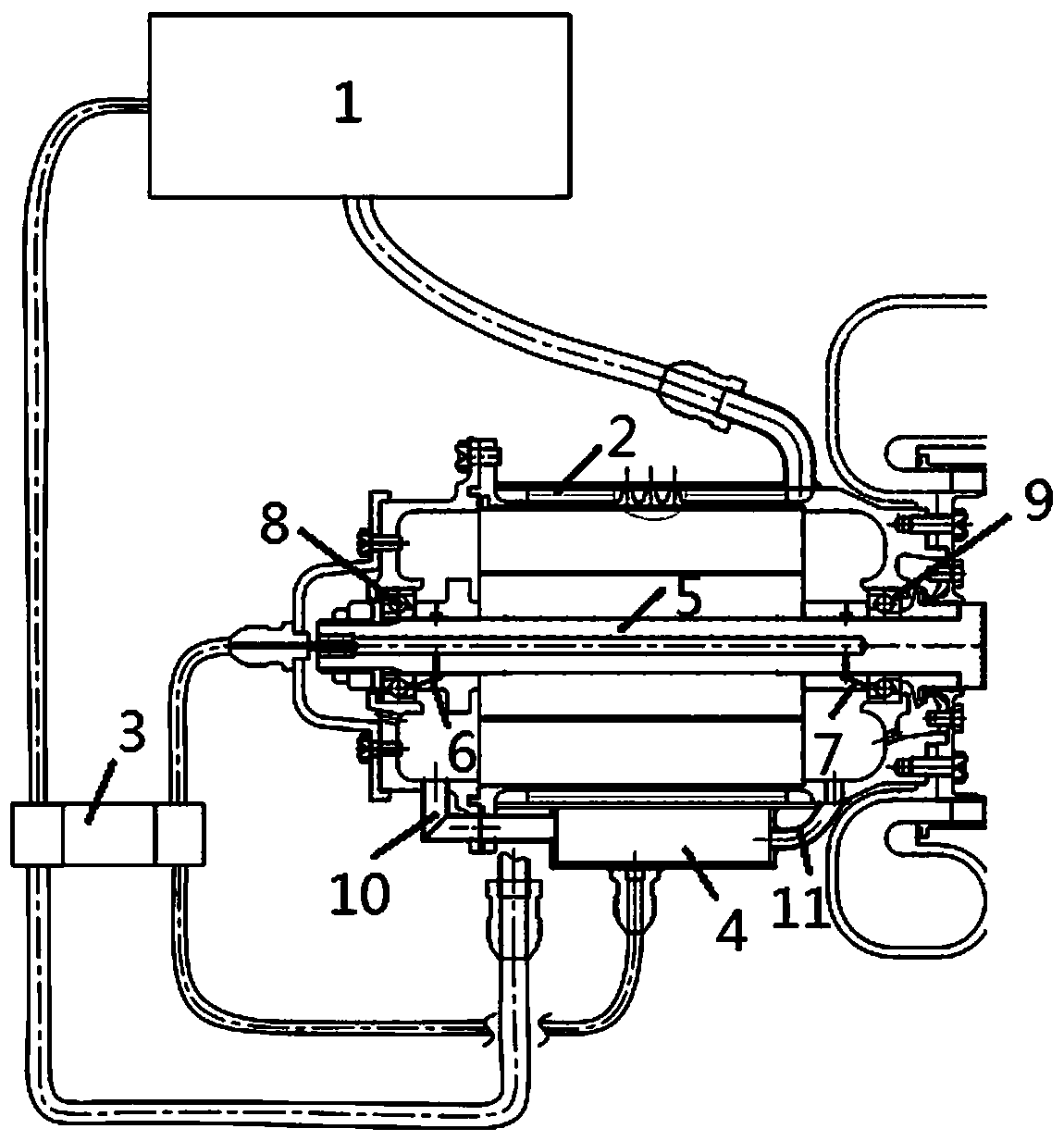
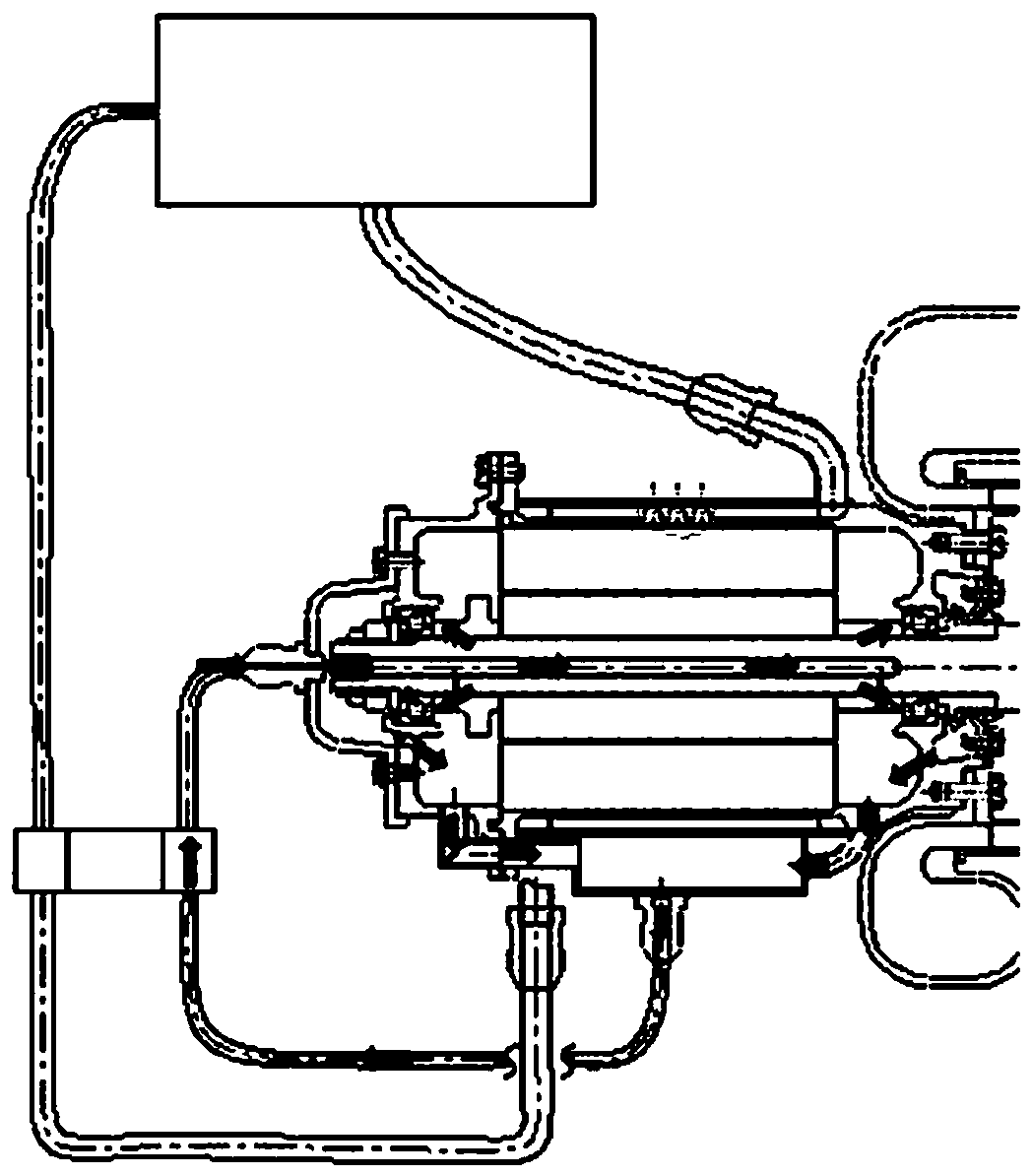
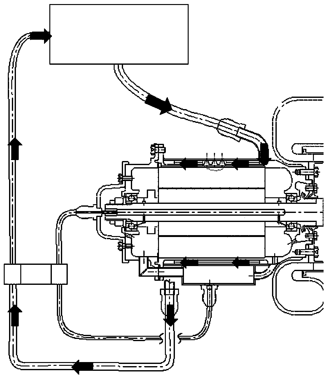
[0029] As shown in the figure, the shaft hole cooling and lubricating system is composed of an internal circulation oil circuit and an external oil circuit. The internal circulation oil circuit includes a double-head oil pump 3, a lubricating oil tank 4, a rotary static joint, and a rotating shaft 5; the double-head oil pump 3 passes through the pipe The oil tank 4 and one end of the rotary static transfer joint are respectively connected to each other, and the other end of the rotary static transfer joint is connected to the rotating shaft 5. The two ends of the rotating shaft 5 are respectively provided with a front pressing plate 6 and a rear pressing plate 7. The front pressing plate, the rear pressing plate and the shaft There is a diversion hole on the top, the diversion hole is connected to the front and rear oil return chambers, and the front and rear oil return chambers are connected to the lubricating oil tank through the front oil return circuit 10 and the rear oil re...


PUM


Abstract

The invention relates to a shaft hole cooling and lubricating system, which is composed of an internal circulating oil circuit and an external oil circuit. The internal circulating oil circuit includes an oil pump, a lubricating oil tank, a rotary static joint, and a rotating shaft; the external oil circuit includes a cooling jacket, an oil pump, Main fuel tank: Compared with other cooling and lubricating systems, the device of the present invention has the characteristics of simple structure and few parts, which is easy to realize processing, can greatly reduce the thickness of the outer case and the space of the generator, and reduce the weight of the system ; Reduce processing difficulty; and this device adopts double oil circuit structure, the effect of cooling and lubricating is obvious.

Description

technical field [0001] The invention relates to a shaft hole cooling and lubricating system for cooling and lubricating a high-speed generator in a microturbine power generation system. Its technology belongs to the field of cooling and lubrication, and can be used for cooling and lubrication of miniature high-speed power generation systems in the aerospace field that are sensitive to weight and size and have serious heat generation. Background technique [0002] In the field of aerospace, microturbine power generation systems have relatively strict restrictions on space and weight. Because the high-speed and high-power power generation system will generate a lot of heat during the working process; in the micro-ram turbine power generation system, in order to save space and weight, the distance between the generator and the turbine is relatively close, and a large amount of heat in the turbine will be transferred to the generator; At the same time, the continuous and stable...

Claims


Application Information

Patent Timeline
Patent Type & Authority Patents(China)
IPC IPC(8): H02K9/19F16N7/38
CPCH02K1/32H02K9/19H02K5/203
Inventor 倪瑞林黄国平傅鑫康剑雄韩冬张景峰申春艳
Owner SHENYANG AEROSPACE XINGUANG GRP
Why Eureka
Try Eureka