Photovoltaic support with guide rails

A photovoltaic support and guide rail technology, which is applied in the support structure of photovoltaic modules, photovoltaic power generation, photovoltaic modules, etc., can solve the problems of time-consuming and laborious maintenance or replacement of photovoltaic modules, and achieve the goal of increasing the laying area, increasing the number of laying, and improving installation efficiency Effect

Inactive Publication Date: 2015-12-16
JIANGSU MODERN ENERGY MICROGRID SYST CO LTD
View PDF6 Cites 4 Cited by
  • Summary
  • Abstract
  • Description
  • Claims
  • Application Information

AI Technical Summary

Problems solved by technology

[0002] The photovoltaic bracket of the front photovoltaic bracket includes uprights, diagonal braces, support beams and fixed rods; when installing the photovoltaic module to the photovoltaic bracket, it is fixed and installed on the fixed rod and the frame of the photovoltaic module by corresponding parts that can be buckled together On the photovoltaic bracket, when the photovoltaic module is installed, if a photovoltaic module installed on the photovoltaic bracket needs to be removed for maintenance or replacement, other photovoltaic modules on the photovoltaic bracket need to be removed first, thus making the maintenance of the photovoltaic module easier. Or replacement is time-consuming and labor-intensive

Method used


Image

  • Photovoltaic support with guide rails
  • Photovoltaic support with guide rails
  • Photovoltaic support with guide rails

Examples


Embodiment 1

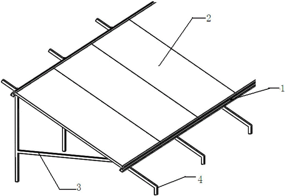
[0016] Embodiment 1: In this embodiment, a photovoltaic support with guide rails, its structure schematic diagram is as follows figure 1 As shown, a support frame 3, a support beam 4 and a guide rail device 1 are included. The support beam 4 is arranged above the support frame 3 , and the guide rail device 1 is symmetrically arranged on the support frame 3 .

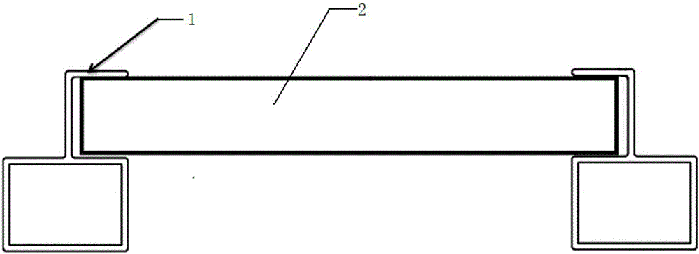
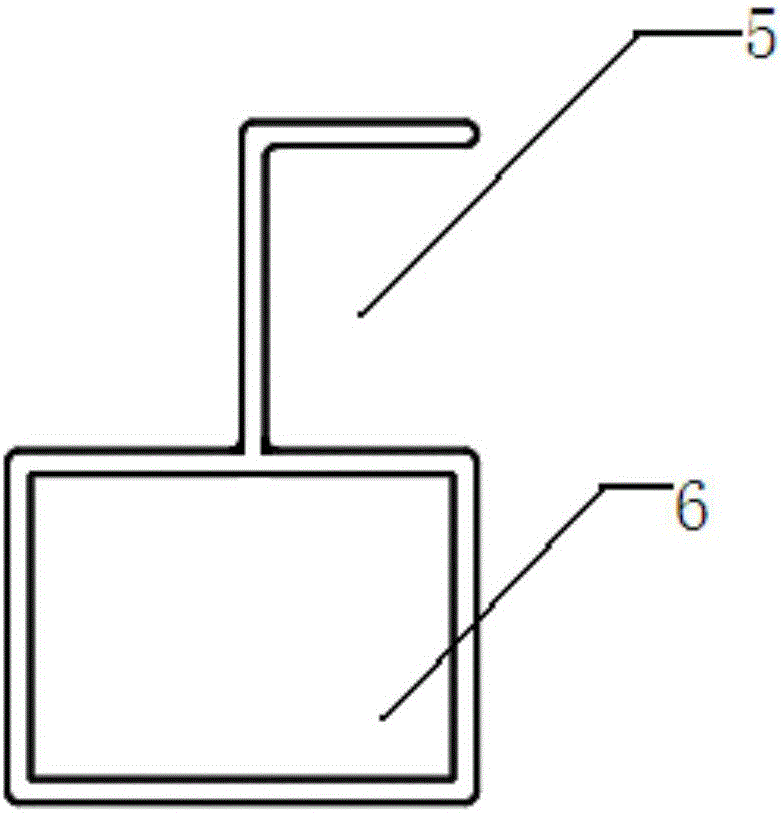
[0017] The material of the rail device 1 is aluminum, including a slot 5, the slot 5 is a right-angle slot, and its structural diagram is as follows: image 3 As shown, the inner surface is a smooth surface, the opening height of the slot 5 is matched with the thickness of the photovoltaic panel 2 to be installed, and the openings of the slots 5 of the two guide rail devices 1 are oppositely arranged. The photovoltaic panel 2 can slide directly in the slot 5 during installation. Since the height of the slot 5 corresponds to the thickness of the photovoltaic panel 2, there is no need to add additional fixing devices, and...

Embodiment 2

[0020] Embodiment 2: A photovoltaic support with guide rail provided in this embodiment, its structure and method of installation and use are basically the same as in Embodiment 1, the difference is: the structural diagram of the guide rail device 1 is as follows Figure 4 As shown, the base 6 and the slotting device are not integrally formed, and the upper bottom surface of the base 6 is provided with a fixing groove that matches the vertical wall of the slotting device, and the vertical wall of the slotting device is fixed on the fixing groove , realize the adjustment of the opening height of the embedded groove 5, and adapt to photovoltaic panels 2 of various thicknesses.

Embodiment 3

[0021] Embodiment 3: A photovoltaic support with guide rail provided in this embodiment, its structure and method of installation and use are basically the same as in Embodiment 1, the difference is: the schematic diagram of the structure of the guide rail device 1 is as follows Figure 5 As shown, the slot 5 is an arc slot, and the height of the opening of the arc slot corresponds to the thickness of the photovoltaic panel 2. Therefore, the photovoltaic panel 2 can slide in the arc slot, and the arc slot The contact area between the embedding groove and the photovoltaic panel 2 is small, which makes the photovoltaic panel easier to slide and easy to install.


PUM


Abstract

A photovoltaic support with guide rails provided by the invention includes a support frame and support beams, the support beams are arranged on the support frame, the photovoltaic support also includes two guide rail devices symmetrically arranged on the support frame, each guide rail device includes an embedding groove, upper and lower surfaces of the embedding groove are smooth surfaces, the opening height of the embedding groove is matched with the thickness of a photovoltaic panel to be installed, and in addition, the openings of the embedding grooves of the two guide rail devices are oppositely arranged. Through the embedding grooves with the smooth surfaces, a photovoltaic module is positioned on the rapid photovoltaic support, the module is only needed to put in the guide rails, and no fixing treatment is additionally needed, thereby improving installation efficiency of the module.

Description

technical field [0001] The invention relates to a photovoltaic support, in particular to a photovoltaic support with guide rails. Background technique [0002] The photovoltaic bracket of the front photovoltaic bracket includes uprights, diagonal braces, support beams and fixed rods; when installing the photovoltaic module to the photovoltaic bracket, it is fixed and installed on the fixed rod and the frame of the photovoltaic module by corresponding parts that can be buckled together On the photovoltaic bracket, when the photovoltaic module is installed, if a photovoltaic module installed on the photovoltaic bracket needs to be removed for maintenance or replacement, other photovoltaic modules on the photovoltaic bracket need to be removed first, thus making the maintenance of the photovoltaic module easier. Or replacement is time-consuming and laborious. Contents of the invention [0003] Purpose of the invention: To address the deficiencies of the current prior art, pr...

Claims


Application Information

Patent Timeline
Patent Type & Authority Applications(China)
IPC IPC(8): H02S20/10
CPCY02E10/50
Inventor 徐拥军赵志国
Owner JIANGSU MODERN ENERGY MICROGRID SYST CO LTD
Why Eureka
Try Eureka