A remote-controlled wall-mounted cooling device

A heat-dissipating device and remote-control technology, applied in the field of remote-control wall-mounted heat-dissipating devices, can solve the problems of low utilization of space inside the cavity, small heat dissipation area, complicated design and installation, etc., so as to save complicated design process, installation and installation. Easy disassembly and effective heat dissipation

Active Publication Date: 2018-03-20
杭州瀚陆海洋科技有限公司
View PDF3 Cites 0 Cited by
  • Summary
  • Abstract
  • Description
  • Claims
  • Application Information

AI Technical Summary

Problems solved by technology

[0003] The first is to paste the circuit board on the end cover through the heat dissipation block to dissipate heat. This heat dissipation method has a relatively simple structure, but the heat dissipation area is small, and the efficiency is lower than that of the side wall heat dissipation.
The second is to make an integral bracket and paste it on the side wall of the cavity to dissipate heat. This wall-attached heat dissipation method has high heat dissipation efficiency, but the design and installation are complicated, and the utilization rate of the internal space of the cavity is low.
[0004] The above three wall-mounted heat dissipation methods all need to be designed according to the specific circuit and cavity structure, which has a great impact on the internal structure of the cavity and poor adaptability

Method used


Image

  • A remote-controlled wall-mounted cooling device
  • A remote-controlled wall-mounted cooling device

Examples


Embodiment Construction

[0017] In order to make the object, technical solution and advantages of the present invention clearer, the present invention will be further described in detail below in conjunction with the accompanying drawings and embodiments. It should be understood that the specific embodiments described here are only used to explain the present invention, not to limit the present invention.

[0018] On the contrary, the invention covers any alternatives, modifications, equivalent methods and schemes within the spirit and scope of the invention as defined by the claims. Further, in order to make the public have a better understanding of the present invention, some specific details are described in detail in the detailed description of the present invention below. The present invention can be fully understood by those skilled in the art without the description of these detailed parts.

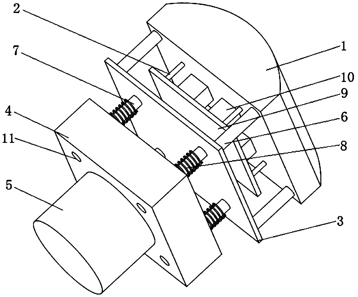
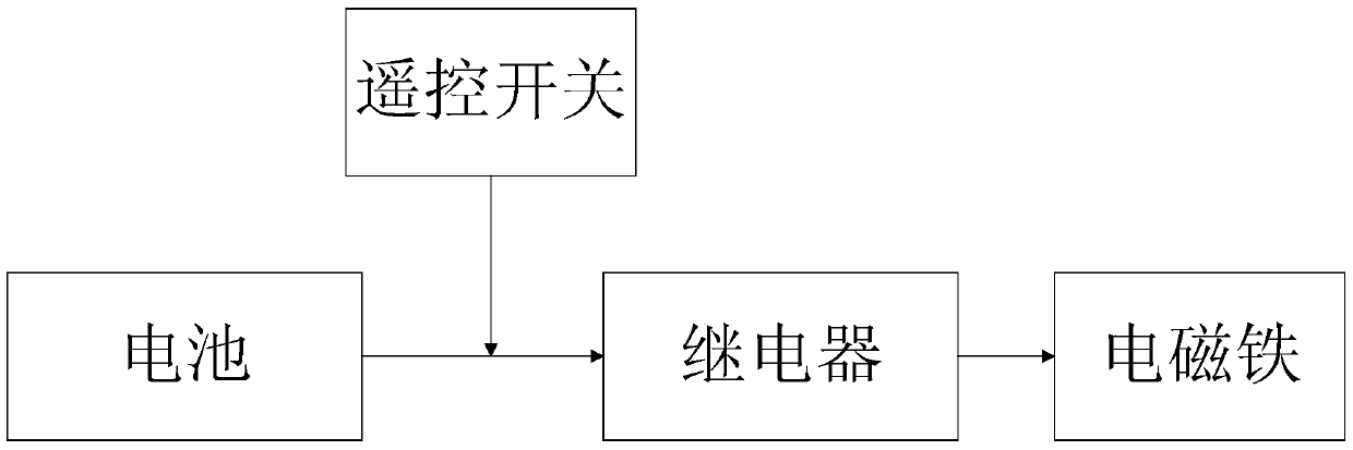
[0019] Such as figure 1 and figure 2 , which are the structure schematic diagram and the control sc...


PUM


Abstract

A remote-controlled wall-mounted cooling device, including a wall-mounted cooling block, a circuit board to be dissipated, a thermal conduction column for fixing the circuit board to be cooled and a wall-mounted cooling block, an iron sheet, a mounting frame, and an electromagnet for controlling The relay of the electromagnet switch and the infrared remote control switch that controls the action of the relay, the two sides of the iron sheet are respectively connected with a pillar and a cylinder, the other end of the pillar is fixedly connected to the heat sink block attached to the wall, and the other end of the cylinder is movably connected with the mounting frame, The electromagnet is fixedly installed on the bottom of the installation frame. The remote-control wall-attached cooling device of the present invention is easy to install, can adapt to cavities of different sizes, can be installed at any depth of the cavity, does not affect the installation and disassembly of each module of the cavity, and can be very effectively adhered to the wall for heat dissipation.

Description

technical field [0001] The invention belongs to the field of underwater electromechanical heat dissipation devices, and relates to a remote-controlled wall-mounted heat dissipation device for heat dissipation in an underwater pressure-resistant cavity. Background technique [0002] The current underwater electromechanical equipment often needs to be equipped with a sealed pressure-resistant cavity for the placement of various circuits. When the power of the circuit is large, heat dissipation becomes a problem that cannot be ignored. The underwater high-power regulated power supply, inverter circuit, etc. need to be fully dissipated. Since the cavity itself is a closed environment, the air convection heat dissipation effect in the cavity is very poor. Therefore, high-power heat dissipation often requires the heat source to be attached to the cavity wall. Since there is cold water outside the cavity wall, this heat dissipation method has high efficiency and is an ideal underw...

Claims


Application Information

Patent Timeline
Patent Type & Authority Patents(China)
IPC IPC(8): H05K7/20
Inventor 史剑光于海滨刘敬彪潘勉孔庆鹏盛庆华江晓
Owner 杭州瀚陆海洋科技有限公司
Why Eureka
Try Eureka