Novel fire extinguisher

A fire extinguisher and a new type of technology, applied in fire rescue and other directions, can solve problems such as personal injury, injury to users, and large momentum, and achieve the effects of reducing injury, ensuring explosion venting safety, and preventing explosion and deflagration.

Active Publication Date: 2015-12-23
SUZHOU LONG PORT FIRE CONTROL EQUIP
View PDF6 Cites 0 Cited by
  • Summary
  • Abstract
  • Description
  • Claims
  • Application Information

AI Technical Summary

Problems solved by technology

[0002]Existing portable fire extinguishers are widely used. Although the structure of portable fire extinguishers is small, in some cases, the pressure may be too large to cause explosion and deflagration. As a result, the fire extinguisher will generate a strong recoil force, which will injure the user. At the same time, during the deflagration and explosion, debris will be generated or the objects at the nozzle will break away from the body, causing unexpected damage to the surrounding people and property.
For example, in a portable aerosol fire extinguisher, when the powder column in the inner cylinder deflagrates, due to its small nozzle, the hot aerosol gas will accumulate rapidly in the cylinder, and the pressure in the cylinder will rise sharply, so the heat energy will be converted into huge kinetic energy. On the cylinder body, one part pushes the cylinder cover forward along the direction of the spout, while the other part acts on the cylinder body to generate recoil force in the opposite direction, which will cause serious personal injury when it acts on the user. In addition, due to its high momentum, the flushed cylinder cover will cause accidental injury to the surrounding people or objects after breaking away from the cylinder.

Method used


Image

  • Novel fire extinguisher
  • Novel fire extinguisher
  • Novel fire extinguisher

Examples


Embodiment Construction

[0019] The technical solutions of the present invention will be further described below in conjunction with the accompanying drawings and specific embodiments.

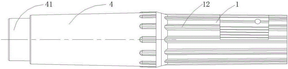
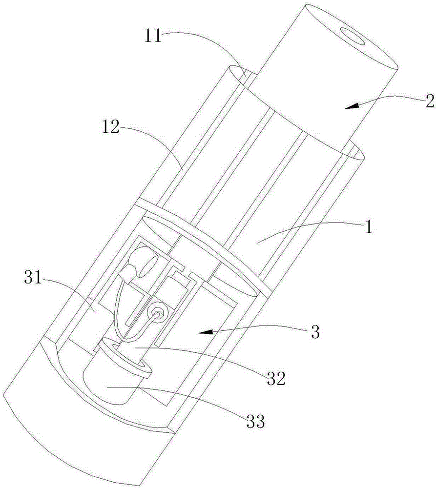
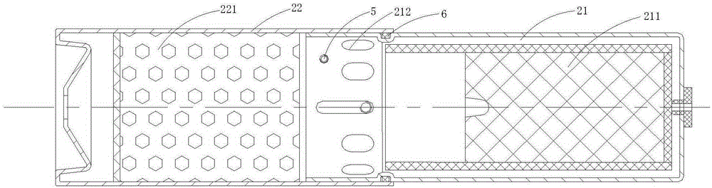
[0020] see figure 1 , figure 2 , image 3 As shown, a new type of fire extinguisher includes an outer shell 1 and an inner cylinder 2 inserted in the shell cavity of the outer shell 1 . The inner cylinder 2 includes a first inner cylinder 21 which stores a fire extinguishing agent 211 and is inserted in the cavity of the outer shell 1 along the front-rear direction, and a first inner cylinder 21 which stores a coolant and is slidably sleeved on the outer wall of the front end of the first inner cylinder 21 . 221 of the second inner cylinder 22, the inner cylinder 2 also includes an explosion vent 212 provided on the side wall of the first inner cylinder 21, and an explosion vent 212 provided on the side wall of the second inner cylinder 22. On or away from the shielding part of the explosion vent 212, the e...


PUM


Abstract

The invention discloses a novel fire extinguisher which comprises an outer shell and an internal cylinder inserted in an outer shell cavity, wherein the internal cylinder comprises a first internal cylinder, a second internal cylinder, an explosion venting opening and a shielding part; the first internal cylinder is inserted in the outer shell cavity in the front-back direction and stored with an extinguishant; the second internal cylinder is slidingly arranged on the side wall of the front end of the first internal cylinder in a sleeving manner and stored with a coolant; the explosion venting opening is formed in the side wall of the first internal cylinder; the shielding part is arranged on the side wall of the second internal cylinder, shields the explosion venting opening, or is away from the explosion venting opening; the explosion venting opening is formed in the outer shell cavity; an explosion venting cavity communicated with the atmosphere is formed between the inner surface of the outer shell cavity and the outer side wall of the first internal cylinder. The explosion venting opening is formed in the side wall of the first internal cylinder, so that the internal cylinder is effectively prevented from explosion and deflagration caused by excessively high pressure in the cylinder; in addition, the explosion venting opening is formed in the outer shell cavity, air pressure in the internal cylinder is effectively prevented from being directly discharged from the explosion venting opening to damage a user and the surrounding environment.

Description

technical field [0001] The invention relates to the technical field of fire protection, in particular to a novel fire extinguisher. Background technique [0002] Existing portable fire extinguishers are widely used. Although the structure of portable fire extinguishers is small, in some cases, the pressure accumulation may be too large to cause explosion and deflagration, which will cause strong recoil of the fire extinguisher and injure users. , At the same time, in the process of deflagration and explosion, debris will be produced or the objects at the nozzle will break away from the body, causing unexpected damage to the surrounding people and property. For example, in a portable aerosol fire extinguisher, when the powder column in the inner cylinder deflagrates, due to its small nozzle, the hot aerosol gas will accumulate rapidly in the cylinder, and the pressure in the cylinder will rise sharply, so the heat energy will be converted into huge kinetic energy. On the c...

Claims


Application Information

Patent Timeline
Patent Type & Authority Applications(China)
IPC IPC(8): A62C13/72
Inventor 李忠刘红周玉清
Owner SUZHOU LONG PORT FIRE CONTROL EQUIP
Why Eureka
Try Eureka