
Clamping head

A clamping head and base technology, applied in metal processing, metal processing equipment, manufacturing tools, etc., can solve the problems of easy change, unfavorable high-precision assembly, difficult to guarantee installation accuracy, etc., to prevent offset and high precision. Assembly, highly adaptable effect

Active Publication Date: 2015-12-23
CHENGDU AIRCRAFT INDUSTRY GROUP +1
View PDF6 Cites 2 Cited by
  • Summary
  • Abstract
  • Description
  • Claims
  • Application Information

AI Technical Summary

Problems solved by technology

However, due to the heavy weight of the workpiece, the position and state of the workpiece may change during the installation process. If the traditional clamping head is used, the position of the workpiece relative to the fixture is likely to change, and the installation accuracy is difficult to guarantee, which is not conducive to the completion of high-precision assembly

Method used


Image

  • Clamping head
  • Clamping head
  • Clamping head

Examples


Embodiment Construction

[0059] The clamping head of the present invention will be described in detail below with reference to the accompanying drawings.

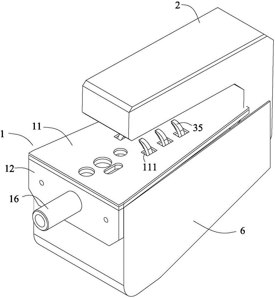
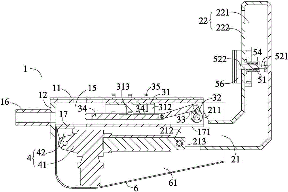
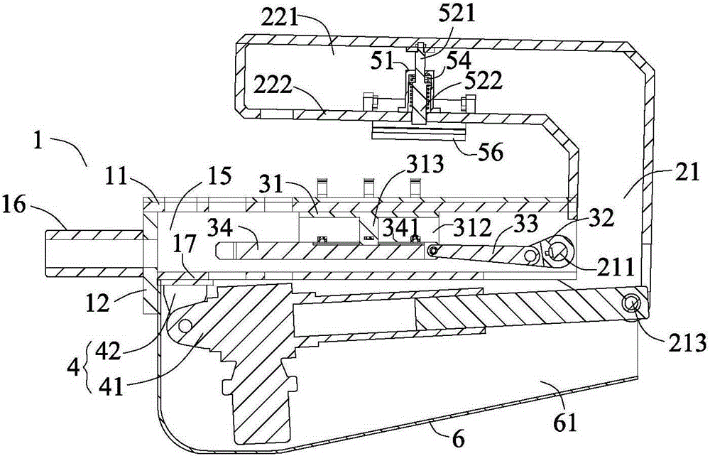
[0060] refer to Figure 1 to Figure 10 , The clamping head according to the present invention includes a base 1 , an overturn frame 2 , a finger fixing mechanism 3 , a driving mechanism 4 and a pressing block fixing mechanism 5 .

[0061] The base 1 is mounted on an external driving mechanism (not shown), and has: a top plate 11, provided with a plurality of first openings 111, arranged in two rows along the length direction; an end plate 12, connected to the front end of the top plate 11; and a left side plate 13 and the right side plate 14 are arranged on both sides of the end plate 12 and form a first cavity 15 with the top plate 11 and the end plate 12 .

[0062]The turning frame 2 has a connecting portion 21 and a turning portion 22 . The connecting part 21 has: a first rotating shaft 211, the two ends of which are pivotally connected to the...


PUM


Abstract

The invention provides a clamping head which comprises a base, a turning support, a finger fixing mechanism, a driving mechanism and a press block fixing mechanism, wherein the base is mounted on an external driving mechanism, and comprises a top plate, an end plate, a left side plate, a right side plate and a first cavity in the interior; the turning support comprises a connecting part and a turning part; the finger fixing mechanism comprises a fixing platform, a crank, a connecting rod, a sliding platform, a plurality of mechanical fingers and a plurality of ball joint connecting rods; the driving mechanism comprises a push-rod motor; the press block fixing mechanism comprises a shaft sleeve, a core shaft, two bending arms, a spring, two short connecting rods and two press blocks; each press block comprises a press block connecting part and a contact part. According to the clamping head provided by the invention, the mechanical fingers of different shapes can effectively fix workpieces of different shapes, so that the adaptability is relative high; the mechanical fingers and the contact parts of the press block jointly act on the upper and lower parts of a workpiece, so that the workpiece can be automatically clamped and prevented from migrating in moving and assembly processes, and high-precision assembly of the workpiece can be realized.

Description

technical field [0001] The invention relates to a clamping device, in particular to a clamping head. Background technique [0002] In the assembly process of small batches of large and heavy-duty workpieces, due to the small number of workpieces of each type and the incomplete shape of the workpieces, it is not economical to develop special fixtures, so general-purpose fixtures with certain adaptability are generally used to fix the workpieces. One of the more common ways is to fix the workpiece with the clamping force of the clamping head by installing a clamping head at the end of the gripper. However, due to the large weight of the workpiece, the position and state of the workpiece may change during the installation process. If the traditional clamping head is used, the position of the workpiece relative to the fixture is likely to change, and the installation accuracy is difficult to guarantee, which is not conducive to the completion of high-precision assembly. Conten...

Claims


Application Information

Patent Timeline
Patent Type & Authority Applications(China)
IPC IPC(8): B23P19/00
CPCB23P19/006
Inventor 帅朝林陈雪梅徐静陈恳刘炽成王国磊宋立滨杨向东
Owner CHENGDU AIRCRAFT INDUSTRY GROUP
Learn More