
Overturning and correction mechanism of backlight source module laminator

A film laminating machine and backlight technology, applied in object supply, pile separation, thin material processing, etc., can solve problems such as difficulty, high stability requirements, and low efficiency, and achieve low cost, high stability, and structural flexibility high effect

Inactive Publication Date: 2015-12-23
CHANG TIAN PRECISION EQUIP
View PDF9 Cites 8 Cited by
  • Summary
  • Abstract
  • Description
  • Claims
  • Application Information

AI Technical Summary

Problems solved by technology

[0002] In the prior art, the backlight module includes several film layers, and the efficiency of manual film application by skilled workers is very low. In order to improve the film application efficiency of the backlight module, an automatic film lamination machine for the backlight module has appeared. The traditional film lamination machine does not have a flip guide Mechanism, the film laminating machine rotates the product through the cylinder, which is very difficult for precision flipping with high stability requirements and fast speed, so it is necessary to improve

Method used


Image

  • Overturning and correction mechanism of backlight source module laminator
  • Overturning and correction mechanism of backlight source module laminator

Examples


Embodiment Construction

[0017] The present invention will be described in further detail below in conjunction with the embodiments and with reference to the accompanying drawings.

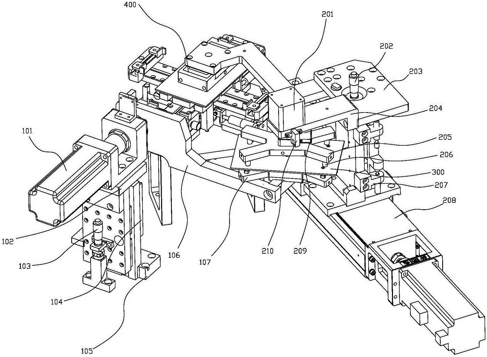
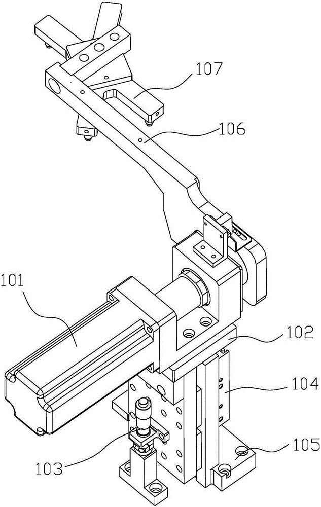
[0018] A flipping and guiding mechanism of a backlight module laminating machine, please refer to Figure 1 to Figure 2 , including an overturning device and a guiding device; the overturning device includes an overturning base 105, on which a rotating arm 106 is rotated, and the end of the rotating arm 106 is provided with a suction cup 107, and the rotating arm 106 rotates When the suction position is reached, the suction cup 107 is facing downward to absorb the diaphragm (refer to figure 2 ), when the rotating arm 106 rotates to the guiding position, the suction cup 107 releases the diaphragm upwards (refer to figure 1 ); the guiding device includes a guiding support plate 204 translated by the conveying device 208, a guiding driving device 201 is fixed on the guiding supporting plate 204, and the guiding driving dev...


PUM


Abstract

The invention discloses an overturning and correction mechanism of a backlight source module laminator. The overturning and correction mechanism of the backlight source module laminator comprises an overturning device and a correction device. The overturning device comprises an overturning base, a rotary arm is rotationally arranged on the overturning base, and a sucker is arranged at the end of the rotary arm. When the rotary arm rotates to the material sucking position, the sucker sucks a diaphragm downwards. When the rotary arm rotates to the correction position, the sucker releases the diaphragm upwards. The correction device comprises a correction supporting plate horizontally moved through a conveying device, a correction driving device is fixed to the correction supporting plate and drives a suction nozzle installation plate to rotate, and a plurality of suction nozzles are arranged on the lower surface of the suction nozzle installation plate. When the correction supporting plate moves horizontally to a limitation position, the suction nozzles are located on the upper surface of a rotary arm correction position diaphragm. When the correction supporting plate moves horizontally to another limitation position, the suction nozzles suck the diaphragm to the next work procedure position. The overturning and correction mechanism of the backlight source module laminator has the advantages of being simple in structure, low in cost, high in speed and high in stability.

Description

technical field [0001] The invention relates to the field of film pasting, in particular to a flipping and guiding mechanism of a backlight module film pasting machine with simple structure, low cost, high speed and high stability. Background technique [0002] In the prior art, the backlight module includes several film layers, and the efficiency of manual film application by skilled workers is very low. In order to improve the film application efficiency of the backlight module, an automatic film lamination machine for the backlight module has appeared. The traditional film lamination machine does not have a flip guide Mechanism, the film laminating machine rotates the product through the cylinder, which is very difficult for precision flipping with high stability requirements and fast speed, so it is necessary to improve it. Contents of the invention [0003] In order to solve the above problems, the object of the present invention is to provide an overturning and guidi...

Claims


Application Information

Patent Timeline
Patent Type & Authority Applications(China)
IPC IPC(8): B65H5/36B65H5/08
Inventor 吴忠文余念华
Owner CHANG TIAN PRECISION EQUIP
Learn More