Shock-absorbing steel structural joint member

A steel structure and node technology, applied in building components, earthquake resistance, building structure, etc., can solve the problems of unreasonable structural design, easy breaking of bolts, poor safety, etc., to enhance safety, protect bolts, and prolong service life. Effect

Inactive Publication Date: 2015-12-23
SICHUAN LANTIAN NET RACK & STEEL STRUCTURE ENG CO LTD
View PDF6 Cites 4 Cited by
  • Summary
  • Abstract
  • Description
  • Claims
  • Application Information

AI Technical Summary

Problems solved by technology

[0004] The joint device disclosed in this patent document, although the truss section is locally strengthened by adding internal partitions and vertical stiffeners, due to unreasonable structural design, the entire joint device forms a rigid connection with the steel column. When the earthquake intensity is high, the bolt It is easy to break, causing the entire node device to be disconnected from the steel column, and the safety is poor

Method used


Image

  • Shock-absorbing steel structural joint member
  • Shock-absorbing steel structural joint member
  • Shock-absorbing steel structural joint member

Examples


Embodiment 1

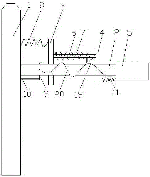
[0033] see figure 1 , a shock-absorbing steel structure node component, including a steel column 1, a channel steel 2, a backing plate 3, a connecting plate 4 and a truss chord 5, one end of the channel steel 2 is connected to the steel column 1, and the other end is connected to the truss chord 5 connection, the channel steel 2 runs through the backing plate 3 and the connecting plate 4 in turn, the backing plate 3 and the connecting plate 4 are connected by bolts 6, the bolts 6 are covered with springs 7, and the backing plate 3 and the steel column 1 pass through The tension spring 8 is connected, the channel steel 2 is covered with a ring 9, and the ring 9 is provided with a stay rope 10, and the circle 9 is connected with the steel column 1 through the stay rope 10, and the connecting plate 4 is connected with the truss string A spring column 11 is arranged between the rods 5, one end of the spring column 11 is connected with the connecting plate 4, and the other end is c...

Embodiment 2

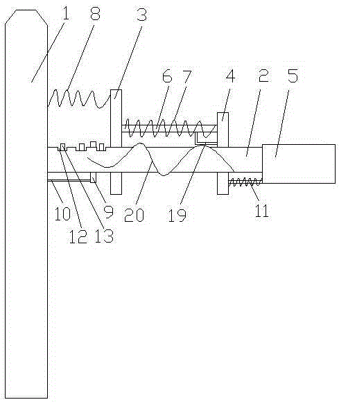
[0036] see figure 2 , a shock-absorbing steel structure node component, including a steel column 1, a channel steel 2, a backing plate 3, a connecting plate 4 and a truss chord 5, one end of the channel steel 2 is connected to the steel column 1, and the other end is connected to the truss chord 5 connection, the channel steel 2 runs through the backing plate 3 and the connecting plate 4 in turn, the backing plate 3 and the connecting plate 4 are connected by bolts 6, the bolts 6 are covered with springs 7, and the backing plate 3 and the steel column 1 pass through The tension spring 8 is connected, the channel steel 2 is covered with a ring 9, and the ring 9 is provided with a stay rope 10, and the circle 9 is connected with the steel column 1 through the stay rope 10, and the connecting plate 4 is connected with the truss string A spring column 11 is arranged between the rods 5, one end of the spring column 11 is connected with the connecting plate 4, and the other end is ...

Embodiment 3

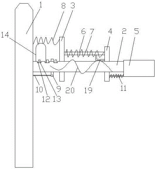
[0040] see image 3 , a shock-absorbing steel structure node component, including a steel column 1, a channel steel 2, a backing plate 3, a connecting plate 4 and a truss chord 5, one end of the channel steel 2 is connected to the steel column 1, and the other end is connected to the truss chord 5 connection, the channel steel 2 runs through the backing plate 3 and the connecting plate 4 in turn, the backing plate 3 and the connecting plate 4 are connected by bolts 6, the bolts 6 are covered with springs 7, and the backing plate 3 and the steel column 1 pass through The tension spring 8 is connected, the channel steel 2 is covered with a ring 9, and the ring 9 is provided with a stay rope 10, and the circle 9 is connected with the steel column 1 through the stay rope 10, and the connecting plate 4 is connected with the truss string A spring column 11 is arranged between the rods 5, one end of the spring column 11 is connected with the connecting plate 4, and the other end is c...


PUM


Abstract

The invention discloses a shock-absorbing steel structural joint member and belongs to the technical field of steel structures. The shock-absorbing steel structural joint member comprises a steel column, a steel channel, a cushion plate, a connecting plate and a truss chord. One end of the steel channel is connected with the steel column, and the other end of the steel channel is connected with the truss chord. The shock-absorbing steel structural joint member is characterized in that the steel channel sequentially penetrates the cushion plate and the connecting plate. The cushion plate is connected with the connecting plate through a bolt sleeved by a spring. The cushion plate is connected with the steel column through a tension spring. The steel channel is sleeved by a circular ring which is provided with a pull rope. The circular ring is connected with the steel column through a pull rope. A spring post is arranged between the connecting plate and the truss chord. One end of the spring post is connected with the connecting plate, and the other end of the spring post is connected with the truss chord. An L-shaped connecting strip is arranged between the bolt and the connecting plate. One end of the L-shaped connecting strip is connected with the bolt, and the other end of the L-shaped connecting strip is connected with the connecting plate. A spiral reinforcing rib is connected to the steel channel. The shock-absorbing steel structural joint member has good shock absorption; the bolt can be effectively protected so that the service life of the whole member is prolonged.

Description

technical field [0001] The invention relates to the technical field of steel structures, in particular to a shock-absorbing steel structure node component. Background technique [0002] In modern buildings, steel structures are often used. Compared with other constructions, the steel structure has advantages in use, design, construction and comprehensive economy, the cost is low, and it can be moved at any time. The specific manifestations are: steel structure residences can better meet the requirements of flexible separation of large bays in buildings than traditional buildings, and can increase the area utilization rate by reducing the cross-sectional area of ​​columns and using light wall panels, and the effective use of indoor areas can be increased. About 6%. The energy-saving effect is good. The wall adopts light and energy-saving standardized C-shaped steel, square steel, and sandwich panels. It has good thermal insulation performance, good earthquake resistance, an...

Claims


Application Information

Patent Timeline
Patent Type & Authority Applications(China)
IPC IPC(8): E04B1/24E04B1/98
Inventor 杨仲
Owner SICHUAN LANTIAN NET RACK & STEEL STRUCTURE ENG CO LTD
Why Eureka
Try Eureka