Using thermal imaging for control of a manufacturing process

Inactive Publication Date: 2012-03-08
GLAXO SMITHKLINE LLC
View PDF22 Cites 17 Cited by
  • Summary
  • Abstract
  • Description
  • Claims
  • Application Information

AI Technical Summary

Benefits of technology

[0036]In preparation of pharmaceutical products using liquid dispensing technology, the temperatures of a large number of carriers in an array to which droplets ar

Problems solved by technology

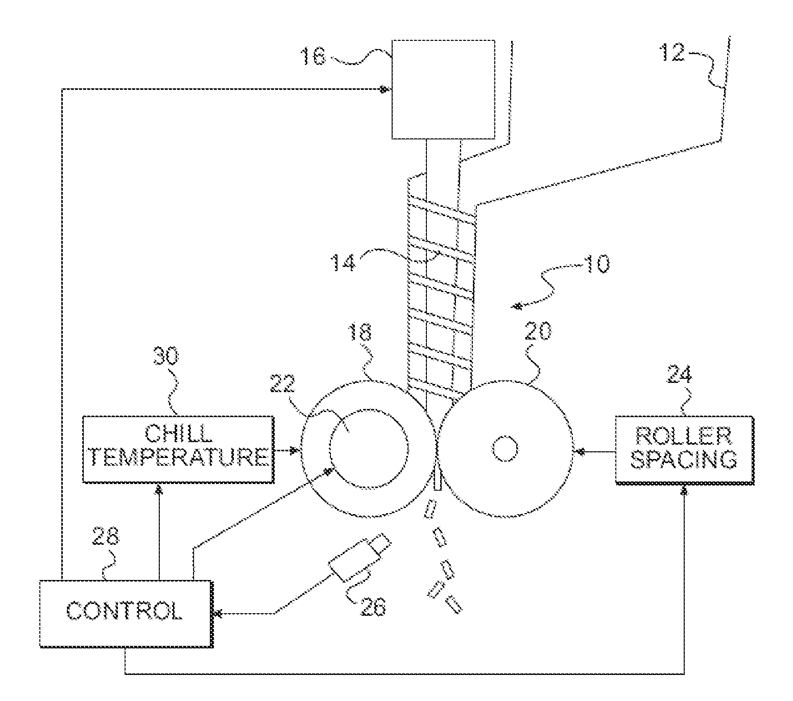
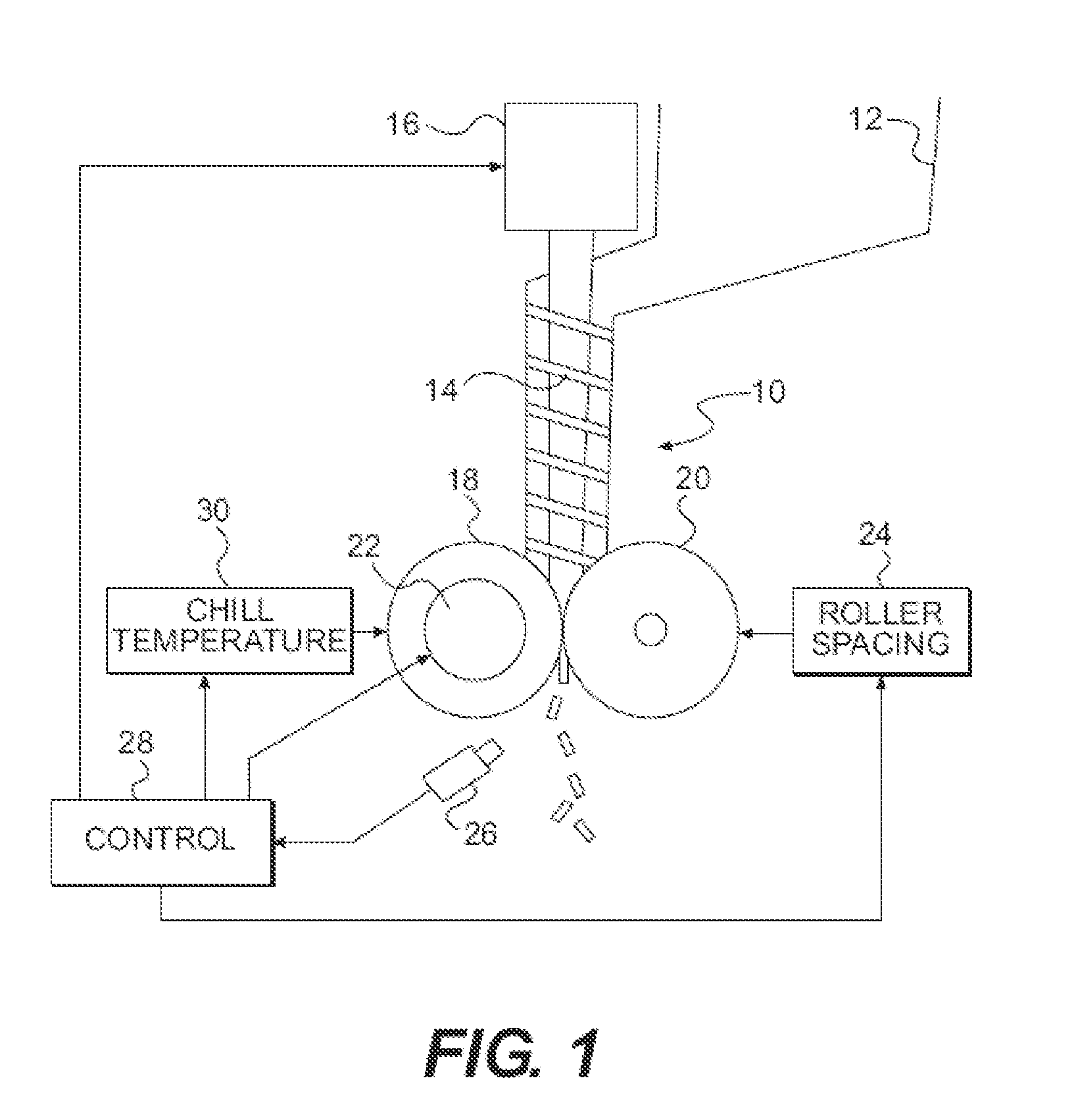
However, product quality problems have been encountered.
It is possible to overcome these problems by making adjusting various parameters of the operation of the compactor, but doing so is difficult and requires a great deal of operator experience.
In addition, some materials that are highly temperature sensitive, and materials that are processed at temperatures near their melting point are particularly susceptible to problems when subjected to roller compaction.
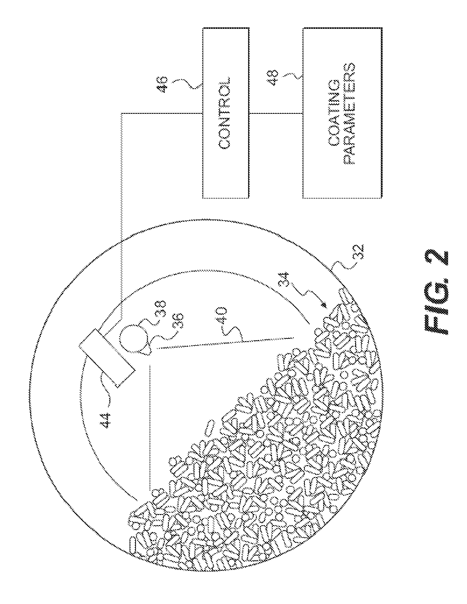
The known temperature measurement devices used for monitoring coating processes do not provide sufficient information for good control of the coating operation, or for designing large coaters by “scaling up” on the basis of temperature measurements taken using a smaller experimental coater.
In particular, known temperature measurement devices used in coaters provide little information concerning the coater spray pattern, and are therefore of limited use in determining the relationship between the rate of flow of coating material through the spray nozzles and the amount of coating deposited on the tablets.
However, as drying proceeds, the temperatures in the upper parts of the dryer increase, and the temperature differences between the upper and lower parts tend to decrease.
Thus, early in a drying operation, the temperature difference is high.
The result is either that excessive drying occurs in the upper zones of the dryer, or the time required for drying decreases.
However, conventional probes do not provide adequate information concerning the progressive changes in temperature differentials that occur over time to enable an operator to control drying parameters such as ai

Method used


Image

  • Using thermal imaging for control of a manufacturing process
  • Using thermal imaging for control of a manufacturing process
  • Using thermal imaging for control of a manufacturing process

Examples


Embodiment Construction

[0047]As shown in FIG. 1, a roller compactor 10 is provided with a hopper 12, for receiving material to be compacted. Material is fed from the hopper, by a feed screw 14 rotated by a motor 16, toward a pair of rollers 18 and 20, which have their outer peripheral surfaces in opposed relationship adjacent the lower end of the feed screw 14. The peripheral surfaces of the rollers can be formed with recesses for molding the material fed by the screw 14 into pellets, and can have various other surface configurations, depending on the desired result. The peripheral surfaces of the rollers can also be simple cylinders.

[0048]Roller 18 is rotated by a motor 22, and coupled by gears or other suitable drive means (not shown) to roller 20, so that both rollers rotate in opposite directions, but at the same peripheral speed.

[0049]An actuator 24, connected to roller 20, is provided to control the relative positions of the axes of rotation of the rollers, and thereby adjust the roller spacing.

[005...


PUM

PropertyMeasurementUnit
Temperatureaaaaaaaaaa
Speedaaaaaaaaaa

Abstract

A thermal imaging camera monitors the temperature different zones in a pharmaceutical process such as ribbon compaction, coating, spray drying, fluid bed drying, high shear wet granulation, crystallization, lyophilization, precipitation, fermentation, and low dosage dispensing of a pharmaceutically active liquid. The thermal imaging camera can be used to produce a visual display of a temperature profile, or a spray pattern. In addition, feedback from the thermal imaging camera is used to control one or more processing parameters.

Description

CROSS-REFERENCE TO RELATED APPLICATION[0001]This application claims the benefit of U.S. provisional application 61 / 178,540 filed 15 May 2009 and of U.S. provisional application 61 / 233,593 filed 13 Aug. 2009.FIELD OF THE INVENTION[0002]This invention relates generally to the manufacture of chemical products such as pharmaceutical products, and particularly to the use of thermal imaging to monitor, and optionally, control, a variety of material processing operations such as roller compaction, tablet coating, fluid bed drying, spray drying, lyophilization, crystallization, precipitation, fermentation, and preparation of low dosage pharmaceutical products using liquid dispensing technology.BACKGROUND OF THE INVENTION[0003]In the manufacture of pharmaceutical products, it is common to utilize an apparatus known as a “roller compactor” to compress a powder composition into a ribbon or into pellets for further processing or utilization. In a roller compactor, the powder composition is fed ...

Claims


Application Information

Patent Timeline
IPC IPC(8): H04N7/18B29C43/58
CPCA61J3/005A61J3/10B01J2/006B01J2/02B01J2/16G01J2005/0085G01J5/0022G01J5/041G01J5/08G01J5/0893B01J2/20B30B11/006B01J2/22G01N25/72G01N33/15G01J5/485A61K9/2893F26B5/06B05D1/02H04N5/33
Inventor ARP, ZANE A.
Owner GLAXO SMITHKLINE LLC
Why Eureka
Try Eureka