Raw material drying device for solid toilet cleaner production

A solid toilet cleaner and drying device technology, which is applied in the direction of drying solid materials, drying, dryers, etc., can solve the problems of insufficient mixing of hot air and materials, so as to prevent poor drying effect, improve the effect, Improve the effect of flow stroke

Active Publication Date: 2020-03-31
株洲蓝海包装有限公司
View PDF6 Cites 2 Cited by
  • Summary
  • Abstract
  • Description
  • Claims
  • Application Information

AI Technical Summary

Problems solved by technology

[0004] Based on the technical problem that the existing drying device cannot fully mix hot air and materials, this invention proposes a raw material drying device for the production of solid toilet cleaners

Method used


Image

  • Raw material drying device for solid toilet cleaner production
  • Raw material drying device for solid toilet cleaner production
  • Raw material drying device for solid toilet cleaner production

Examples


Embodiment 1

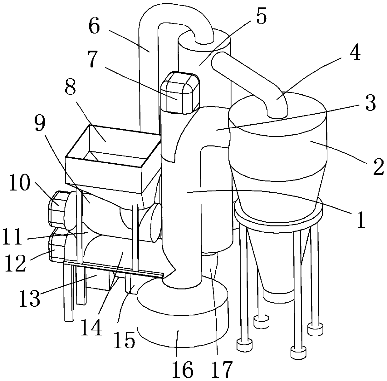
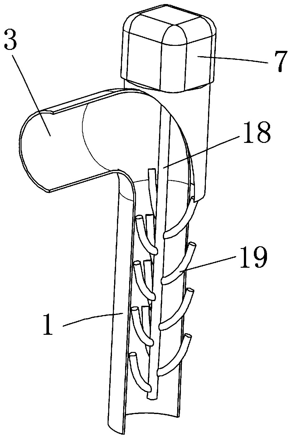
[0030] refer to figure 1 and Figure 5 , a raw material drying device for the production of solid toilet cleaner, comprising a drying cylinder 1, the top of the drying cylinder 1 is provided with a curved end 3, and the top inner wall of the drying cylinder 1 is connected with a stirring shaft 18 through a bearing, the stirring shaft The side outer wall of 18 is welded with stirring rod 19, and the top outer wall of drying drum 1 is connected with stirring motor 7 by screw, and the output shaft of stirring motor 7 is connected to the top outer wall of stirring shaft 18 by shaft coupling, and the top outer wall of drying drum 1 The outer wall of the bottom end is fixedly connected with a heating cylinder 16, and one side of the outer wall of the heating cylinder 16 is plugged with an air guide pipe 17. Bracket 24, the top outer wall of bracket 24 is connected with electric heating pipe 25 by screw, one end of air guide pipe 17 is provided with blower mechanism, one side outer ...

Embodiment 2

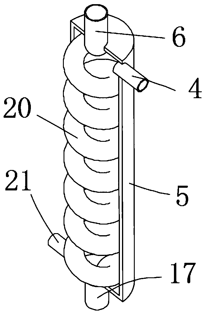
[0036] refer to figure 1 and image 3, a raw material drying device for the production of solid toilet cleaner, compared with embodiment 1, in order to improve the heating effect of the air in the heating cylinder 16, a preheating device is set between one end of the air guide pipe 17 and the outlet end of the blower 15 mechanism, one end of the air outlet pipe 4 is connected with a preheating cylinder 5, and the bottom of one side of the outer wall of the preheating cylinder 5 is provided with an exhaust pipe 21, and the air outlet end of the blower 15 is connected with an air inlet pipe 6, and one end of the air inlet pipe 6 is inserted into Connected to the top outer wall of the preheating tube 5, one end of the air guide tube 17 is plugged into the bottom outer wall of the preheating tube 5, and one end of the air intake tube 6 and one end of the air guide tube 17 are connected with the same preheating tube 20, the preheating tube 20 spiral tubular structure

[0037] Com...


PUM


Abstract

The invention belongs to the technical field of toilet cleaner production, in particular to a raw material drying device for solid toilet cleaner production. In view of the problems that the existingdrying device cannot enable hot air and materials to be fully mixed, the following scheme is put forward: the device comprises a drying cylinder, a bent end is arranged at the top of the drying cylinder, the inner wall of the top of the drying cylinder is connected with a stirring shaft through a bearing, a stirring rod is arranged on the outer wall of the side face of the stirring shaft, a stirring motor is arranged on the outer wall of the top of the drying cylinder, an output shaft of the stirring motor is connected to the outer wall of the top of the stirring shaft through a coupler, a heating cylinder is fixedly connected to the outer wall of the bottom end of the drying cylinder, and an air guide pipe is inserted into the outer wall of one side of the heating cylinder. By means of the drying device, upward-moving powdery raw materials and hot air can be stirred and then fully mixed, the drying effect is improved, the materials can be prevented from adhering to the stirring rod, air in the drying cylinder can be prevented from being exhausted from a feeding hopper, and the air heating effect is improved.

Description

technical field [0001] The invention relates to the technical field of toilet cleaner production, in particular to a raw material drying device for solid toilet cleaner production. Background technique [0002] The solid toilet cleaner is also called toilet cleaner. The characteristics of the toilet cleaner are specially designed for the stubborn stains in the toilet bowl. It can quickly and effectively decompose the stubborn dirt in the toilet bowl. During the production process of the solid toilet cleaner, it is necessary to Some powdered raw materials are dried to prevent agglomeration during subsequent storage. [0003] In the prior art, an air flow drying device is usually used to dry the powder raw materials when drying the powder raw materials. However, when the existing air flow drying device dries the powder raw materials, the powder raw materials are upwardly When exercising, it is easy to be unable to contact with hot air due to the aggregation of powdery raw mat...

Claims


Application Information

Patent Timeline
Patent Type & Authority Applications(China)
IPC IPC(8): F26B11/14F26B21/00F26B25/04
CPCF26B11/14F26B21/002F26B21/004F26B25/04
Inventor 林益平林凤龙熊翠军
Owner 株洲蓝海包装有限公司
Why Eureka
Try Eureka