Restricted type steel tube concrete member

A CFST and concrete technology, applied in bridge parts, bridge construction, columns, etc., can solve the problems of reducing the ductility and weak cross-section of CFST structures

Active Publication Date: 2015-12-23
NANJING FORESTRY UNIV
View PDF10 Cites 3 Cited by
  • Summary
  • Abstract
  • Description
  • Claims
  • Application Information

AI Technical Summary

Problems solved by technology

[0002] In the CFST structure, steel and concrete work together to give full play to their respective advantages, so that the member has good ductility, especially excellent seismic performance. At the same time, the CFST structure has the advantages of convenient construction and high rigidity. However, CFST The structure still has its own inherent deficiencies: 1) The steel pipe must bear both vertical stress and lateral stress, and the steel pipe mainly bears vertical stress; 2) The effect of vertical stress makes the steel pipe inevitably buckle locally failure mode, which reduces the ductility of the CFST structure, and the buckling is difficult to repair
[0003] Under the conditions of commonly used design parameters in engineering, the compressive bearing capacity of conventional steel tube concrete structures is slightly greater than the simple superposition of the vertical bearing capacity of steel tubes and core concrete. The reason is that the steel tubes have a certain restraint on the core concrete. It is equivalent to increasing the vertical bearing capacity of the steel pipe directly by about 1.3 times. If the steel of the steel pipe

Method used


Image

  • Restricted type steel tube concrete member
  • Restricted type steel tube concrete member
  • Restricted type steel tube concrete member

Examples


Embodiment Construction

[0022] In order to have a clearer understanding of the technical features, purposes and effects of the present invention, the specific implementation manners of the present invention will now be described with reference to the accompanying drawings.

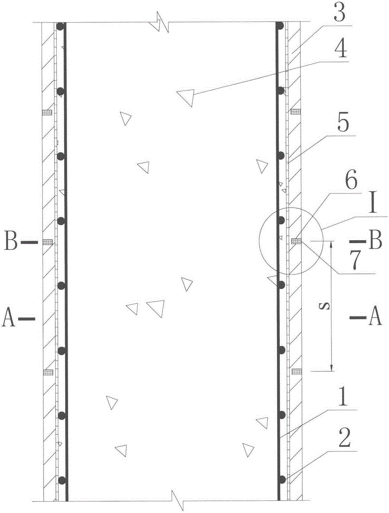
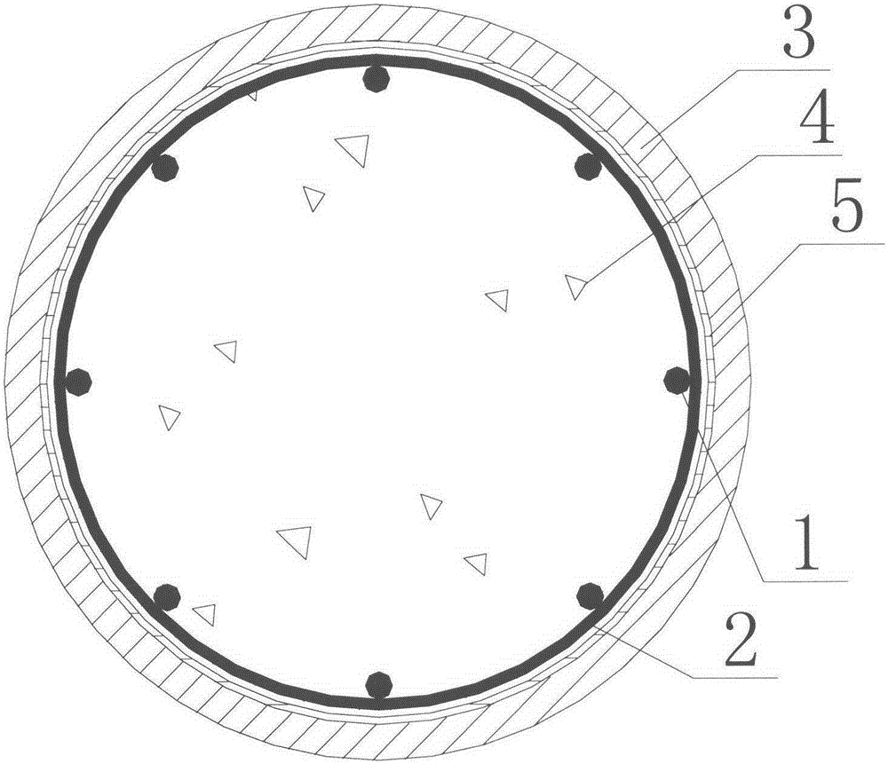
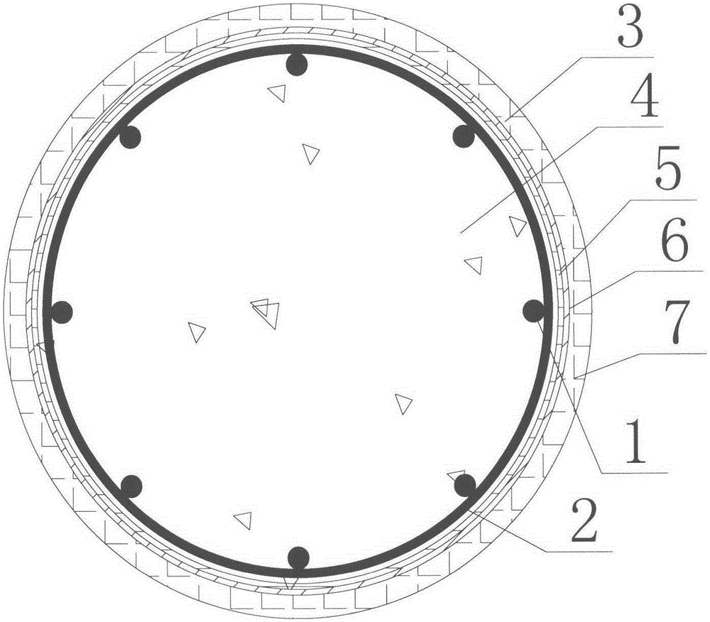
[0023] Such as Figure 1-Figure 6 As shown, the present invention proposes a constrained concrete-filled steel tube member, which is composed of longitudinal bars 1, stirrups 2, steel tubes 3, core concrete 4, and interface layer 5. It is characterized in that the core concrete 4 is filled inside the steel tube 3, and the steel tube 3 There is an interface layer 5 between the core concrete 4, and one or more decompression notches 6 are provided on the surface of the steel pipe 3. The depth of the notch 6 is greater than or equal to 80% of the thickness of the steel pipe 3 and less than the thickness of the steel pipe 3, the sum of the width c of the decompression notch 6 is not less than 2% of the component length, and the fiber ...


PUM


Abstract

A restricted type steel tube concrete member jointly consists of a longitudinal bar (1), a stirrup (2), a steel tube (3), core concrete (4) and a boundary layer (5), and is characterized in that the steel tube (3) is filled with the core concrete (4); the boundary layer (5) is arranged between the steel tube (3) and the core concrete (4); one or more than one pressure reducing notch (6) is formed in the surface of the steel tube (3); the length of each pressure reducing notch (6) equals the annular periphery of the member in the perimeter direction; the depth of each pressure reducing notch (6) is greater than or equals 80% of the thickness of the steel tube (3) and smaller than the thickness of the steel tube (3); the sum of widths of the pressure reducing notches (6) is not smaller than 2% of the length of the member; a fiber reinforced composite material (7) is arranged in each pressure reducing notch (6); and a fiber direction of the fiber reinforced composite material (7) is along the ring direction of the member. The technical shortcoming that the steel tube in a common steel tube concrete structure mainly bears vertical stress and is easy to bend is overcome. The restricted type steel tube concrete member is suitable to be a vertical load-bearing member of various bridges and buildings.

Description

technical field [0001] The invention relates to a restrained steel pipe concrete component, which is applied to various bridges and column structures of buildings, and belongs to the field of civil engineering. Background technique [0002] In the CFST structure, steel and concrete work together to give full play to their respective advantages, so that the member has good ductility, especially excellent seismic performance. At the same time, the CFST structure has the advantages of convenient construction and high rigidity. However, CFST The structure still has its own inherent deficiencies: 1) The steel pipe must bear both vertical stress and lateral stress, and the steel pipe mainly bears vertical stress; 2) The effect of vertical stress makes the steel pipe inevitably buckle locally failure mode, which reduces the ductility of the CFST structure, and the buckling is difficult to repair. [0003] Under the conditions of commonly used design parameters in engineering, the ...

Claims


Application Information

Patent Timeline
IPC IPC(8): E04C3/36E01D19/02
Inventor 魏洋顾冬生端茂军李国芬
Owner NANJING FORESTRY UNIV
Why Eureka
Try Eureka