Electrically heated aircraft composite floor panel

a composite floor panel and aircraft technology, applied in the direction of heating types, energy-efficient board measures, lighting and heating apparatus, etc., can solve the problems of fire safety problems, passive door protection measures, and the structure cannot meet the strength and safety requirements of the aircraft floor panel, so as to prevent overheating and prevent fire hazards

Inactive Publication Date: 2002-11-14
AIRBUS OPERATIONS GMBH
View PDF0 Cites 74 Cited by
  • Summary
  • Abstract
  • Description
  • Claims
  • Application Information

AI Technical Summary

Benefits of technology

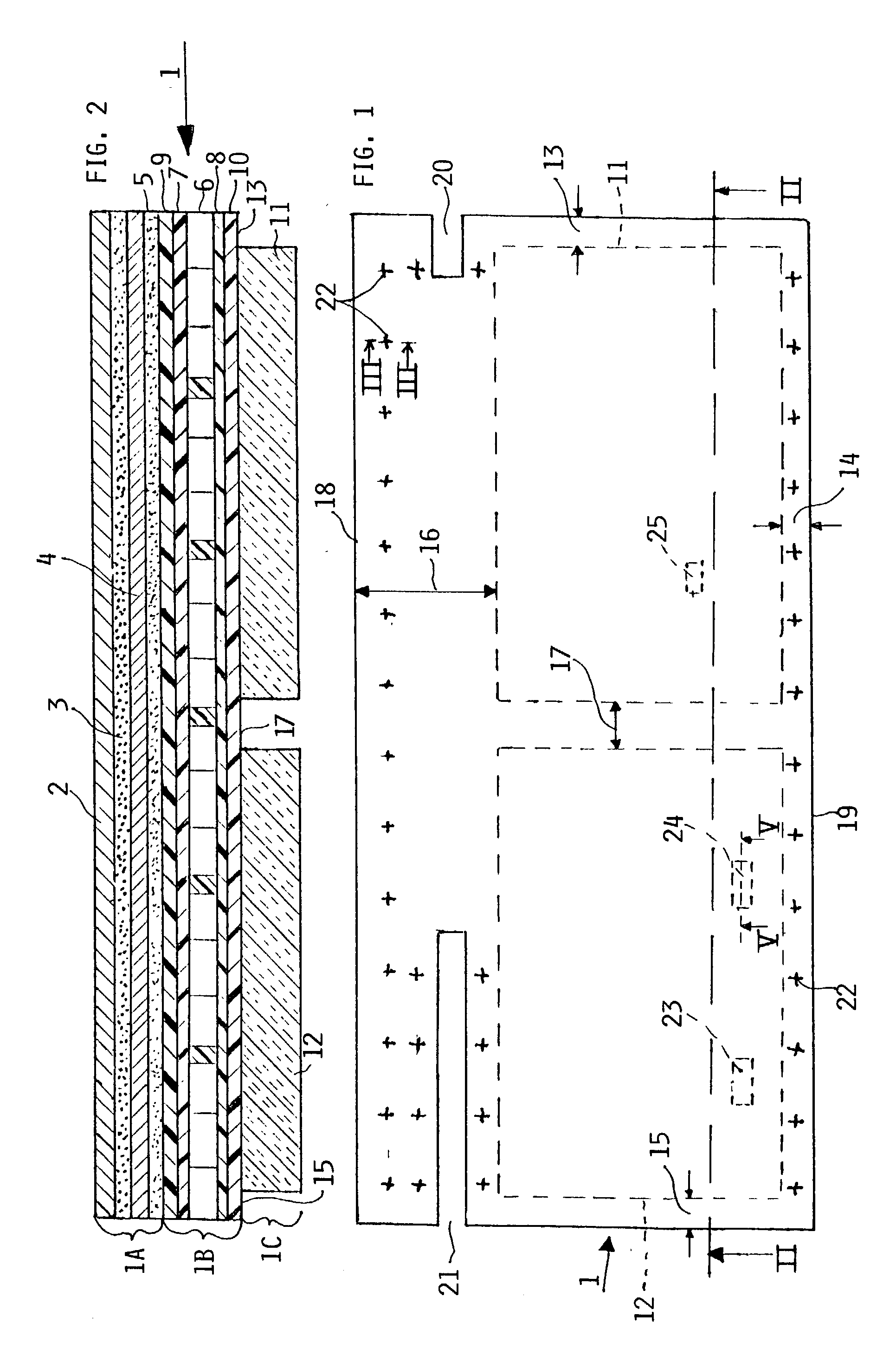
0023] The mechanical strength providing laminated structure comprises a lightweight honeycomb core sandwiched between two inner core protecting layers made of carbon fiber reinforced composite material. The core and CFC layers in turn are sandwiched between two mechanical strength providing glass fiber reinforced composite layers (GFC). This sequence of layers is necessary for obtaining the required protection of the lightweight core by the CFC-layers against deterioration and for obtaining the required mechanical core strength by the GFC-layers bonded to the core through the CFC-layers. The GFC-layers further function as electrical insulating layers to prevent any electrical contact between the CFC-layers and, for example, the heat distributing metal plate or any other metal contact with the floor structure. Further, the CFK layers are electrically grounded for avoiding so-called arc tracking.
0024] The matrix material of the CFC- and GFC-layers is, for example a phenol-formaldehyde resin (PF). The heat distributing metal is preferably made of aluminum which provides a step-on surface and simultaneously a uniform even heat distribution over the surface area of the composite panel. The metal plate also protects the panel, particularly the heater against damage and mechanical stresses.
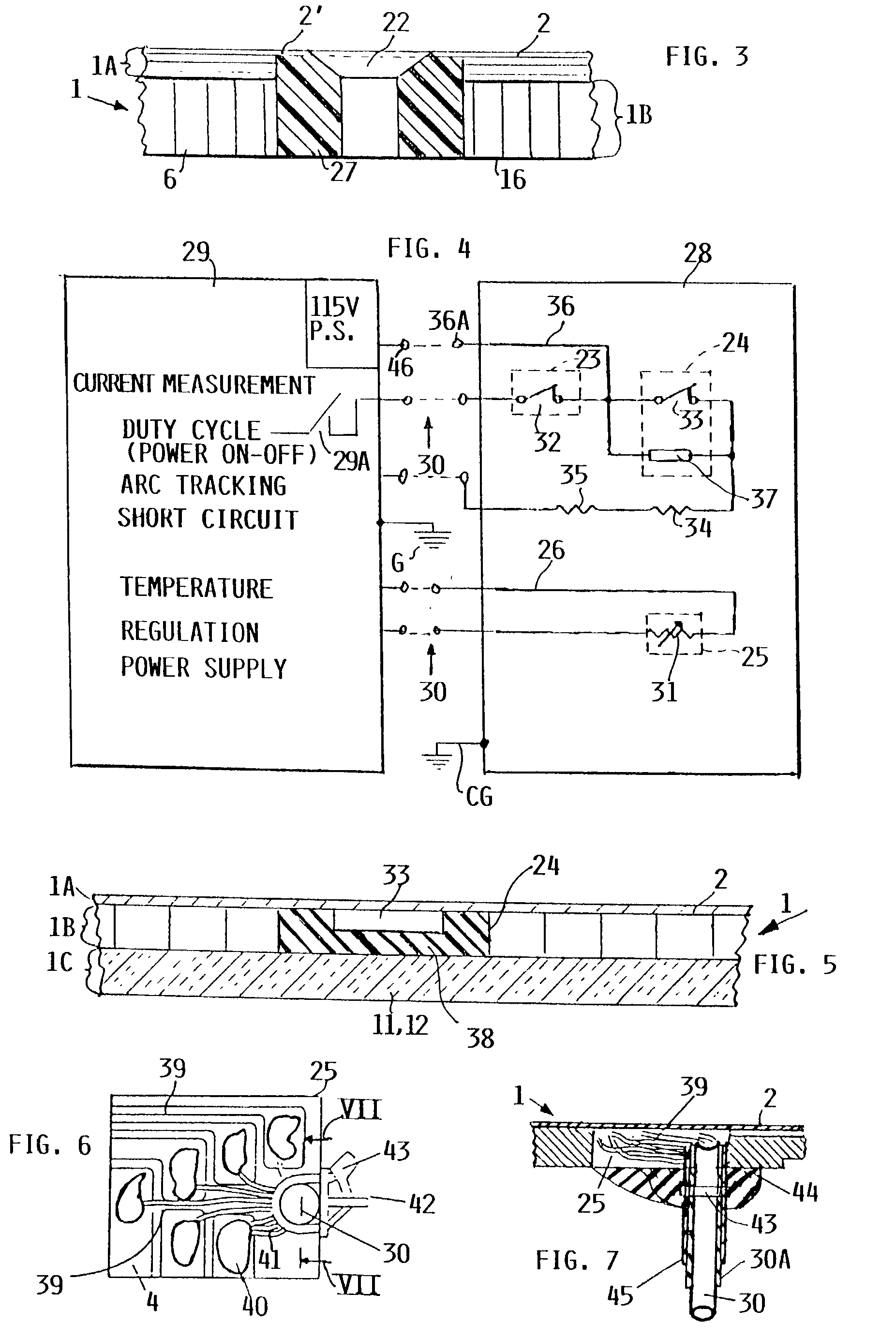
0025] The above mentioned positive temperature coefficient (PTC) sensor in combination with the two thermostatic switches of the present composite panel provides a redundant safety protection against fire hazards. By providing temperature control signals to a control unit the PTC sensor maintains the cabin temperature next to the door in a normal range. At least one, preferably two separate safety thermostatic switches responsive to different temperatures and / or to an excess current, e.g. a short-circuit current, operate independently of the PTC sensor and override the PCT sensor if it fails to prevent an unusual temperature rise. The two safety switches are connected in series with each other in the power supply circuit of the floor panel electric foil heater. For safety reasons it is critical, that the safety switches work independently of each other and independently of the PTC sensor and that the safety switch responsive to the higher temperature or to an excess current can be independently monitored and controlled in its operation. These redundant temperature and / or current controls regulate the temperature of the floor panel to prevent overheating of the panel and thus to prevent a fire hazard.

Problems solved by technology

Such a structure cannot meet the strength and safety requirement of an aircraft floor panel.
In both instances, the panel causes fire safety problems due to the electrical heating.
Passive measures to protect the door area against the cold, such as providing an insulated floor covering, are generally not adequate at such low temperatures and heat energy must be provided to these areas.
The use of warm air systems in aircraft, however, is inefficient for a number of reasons.
These systems also increase the weight of the aircraft and may cause discomfort among passengers and / or flight personnel because of uneven surface temperatures or drafty dry air circulation.
Contamination of the air vents and the danger of blocking air vents by baggage are further disadvantages of warm air heating systems.
This solution also has the disadvantages of adding weight to the aircraft, as well as increasing the high energy consumption.
Because of the combustion properties of such carbon particle mixtures, carbon particle heaters cannot be used in the passenger areas of an aircraft unless extensive safety measures are taken which add to the weight and cost of the aircraft.
Thus, for reasons of safety and economy, such conventional systems are generally unsuitable for use in commercial passenger aircraft.
Each of these publications relates to building construction and does not meet aircraft safety requirements.

Method used


Image

  • Electrically heated aircraft composite floor panel
  • Electrically heated aircraft composite floor panel
  • Electrically heated aircraft composite floor panel

Examples


Embodiment Construction

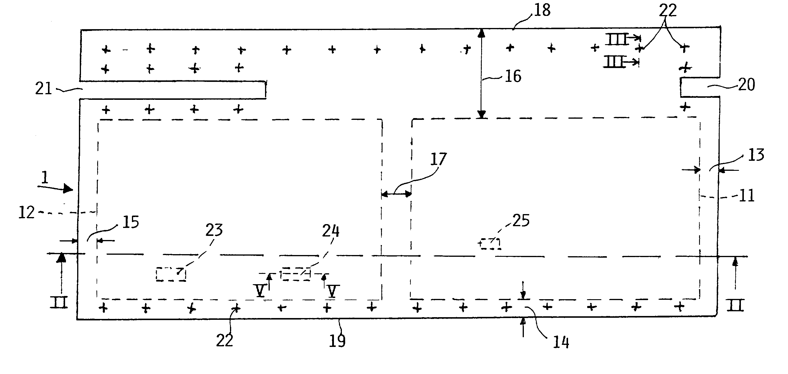
[0040] FIGS. 1 and 2 show an example of the present panel 1. FIG. 1 is a top plan view of an electrically heated aircraft composite floor panel 1 according to the invention. FIG. 2 shows in its sectional view along section line II-II in FIG. 1 the structural details of the present panel. The panel 1 has a heater and step on section 1A, a mechanical strength providing fiber composite core section 1B and a heat insulating section 1C with the core section 1B sandwiched between sections 1A and 1C. The heater and step-on section 1A of the panel 1 comprises a heat distribution metal plate 2 preferably of aluminum which covers the upper surface of the composite panel 1 and provides protection against mechanical stress. The metal plate 2 also assures an even heat distribution over the surface area of the panel 1. A relatively thin, approximately 0.5 mm thick, surface treated metal plate can serve for this heat distribution purpose. The plate 2 made of aluminum is capable of a rapid heat tra...


PUM


Abstract

An aircraft floor heating panel is constructed for mechanical strength and to meet special heating requirements next to a door in an aircraft. The panel has a lightweight core. Each surface of the core is first covered with at least one carbon-fiber reinforced composite layer for protection against deterioration. Each carbon fiber layer in turn is covered by a glass fiber reinforced composite layer for mechanical strength. A foil heater is arranged inside the composite panel coextensive with at least a portion of the panel area. A heat distributing metal plate covers the panel as an upper step-on surface. A heat insulating layer is bonded to the panel opposite the heat distributing metal plate. A triple heat control is provided for an increased safety against fire hazards.

Description

[0001] This application is a Continuation-In-Part Application of copending application Ser. No. 09 / 552,638, filed Apr. 19, 2000.PRIORITY CLAIM[0002] This application is based on and claims the priority under 35 U.S.C. .sctn.119 of German Patent Application 199 18 736.3, filed on Apr. 24, 1999, the entire disclosure of which is incorporated herein by reference. This priority is claimed through the copending parent case U.S. Ser. No. 09 / 552,638, filed on Apr. 19, 2000.[0003] The invention relates to electrically heated aircraft floor panels made as composite material panels, particularly for use as a floor panel directly securable to a floor support grid structure of an aircraft. The panel comprises several layers and a lightweight core such as an open-cell or honeycomb core, and at least one step-on cover layer.BACKGROUND INFORMATION[0004] Conventional composite material panels including an electrical heater are known as sandwich panels and are referred to herein as composite panels ...

Claims


Application Information

Patent Timeline
Patent Type & Authority Applications(United States)
IPC IPC(8): B64C1/18B64C1/40B64D13/08F24D13/02
CPCB64C1/18B64C1/40B64D13/08Y02B30/26Y02T50/44Y02T50/46Y02T50/56F24D13/024Y02B30/00Y02T50/40Y02T50/50
Inventor MEISIEK, JUERGEN
Owner AIRBUS OPERATIONS GMBH
Why Eureka
Try Eureka