Alarm triggering structure of anti-theft timed alarm device for intelligent home system
A technology of smart home system and anti-theft device, which is applied in the direction of electric alarm lock, building structure, building lock, etc., can solve the problems such as the increase of false alarm probability, achieve the effect of solving wiring problems and increasing practicability
- Summary
- Abstract
- Description
- Claims
- Application Information
AI Technical Summary
Problems solved by technology
Method used
Image

Examples
Embodiment 1
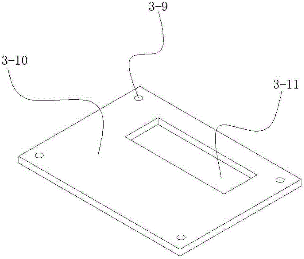
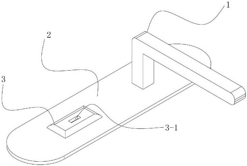
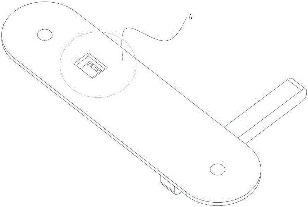
[0024] An alarm trigger structure of a timed alarm anti-theft device for a smart home system, which includes an alarm circuit and an alarm trigger structure, the alarm trigger structure includes a trigger box 3, and the trigger box 3 is provided with a rectangular cavity 3-6, a rectangular cavity 3 -6 is provided with a switch seat 3-2, one end of the switch seat 3-2 is provided with an inclined plane 3-8, the other end is provided with a spring positioning rod 3-3, and the inclined plane 3-8 communicates with the key arranged in the cavity. Hole 2-7 cooperates, and the side wall of rectangular cavity 3-6 inner wall is also provided with the hole 3-4 that cooperates with spring positioning rod 3-3, and spring positioning rod 3-3 inserts in the hole, and spring positioning rod 3-3 A spring is installed on the inner wall of the rectangular cavity 3-6, and an electrode contact 3-2-2 is arranged on the inner wall of the rectangular cavity 3-6. .
Embodiment 2
[0026] An alarm trigger structure of a timed alarm anti-theft device for a smart home system, which includes an alarm circuit and an alarm trigger structure, the alarm trigger structure includes a trigger box 3, and the trigger box 3 is provided with a rectangular cavity 3-6, a rectangular cavity 3 -6 is provided with a switch seat 3-2, one end of the switch seat 3-2 is provided with an inclined plane 3-8, the other end is provided with a spring positioning rod 3-3, and the inclined plane 3-8 communicates with the key arranged in the cavity. Hole 2-7 cooperates, and the side wall of rectangular cavity 3-6 inner wall is also provided with the hole 3-4 that cooperates with spring positioning rod 3-3, and spring positioning rod 3-3 inserts in the hole, and spring positioning rod 3-3 A spring is installed on the inner wall of the rectangular cavity 3-6, and an electrode contact 3-2-2 is arranged on the inner wall of the rectangular cavity 3-6. . The alarm trigger structure also i...
Embodiment 3
[0028] On the basis of embodiment 1-2, the alarm circuit includes a 555 timer alarm circuit, the power switch of the 555 timer alarm circuit is turned on or off through the alarm trigger structure, and the 555 timer alarm circuit is connected with a power self-locking circuit, when When the 555 timer alarm circuit reports to the police, the self-locking circuit connects the power supply for the 555 timer alarm circuit. This application is not limited to the 555 timing alarm circuit for alarming, and other alarm circuits such as based on single-chip microcomputers or DSP, CPLD processors can also be used. The main purpose of this application is to set a touch on the door lock, which combines the alarm circuit to achieve the purpose of anti-theft .
[0029] The 555 timer is a medium-scale integrated device that combines analog circuits and digital circuits. It has excellent performance and a wide range of applications. A small amount of resistance-capacitance components can be c...
PUM
 Abstract
Description
Claims
Application Information
 - R&D
- Intellectual Property
- Life Sciences
- Materials
- Tech Scout
- Unparalleled Data Quality
- Higher Quality Content
- 60% Fewer Hallucinations
Browse by: Latest US Patents, China's latest patents, Technical Efficacy Thesaurus, Application Domain, Technology Topic, Popular Technical Reports.
© 2025 PatSnap. All rights reserved.Legal|Privacy policy|Modern Slavery Act Transparency Statement|Sitemap|About US| Contact US: help@patsnap.com