Hydraulic transformer
A technology for hydraulic transformers and hydraulic cylinders, applied in the field of hydraulic transformers, can solve the problem that AC hydraulic transformers cannot be applied to DC hydraulic systems, etc.
- Summary
- Abstract
- Description
- Claims
- Application Information
AI Technical Summary
Problems solved by technology
Method used
Image
Examples
Embodiment Construction
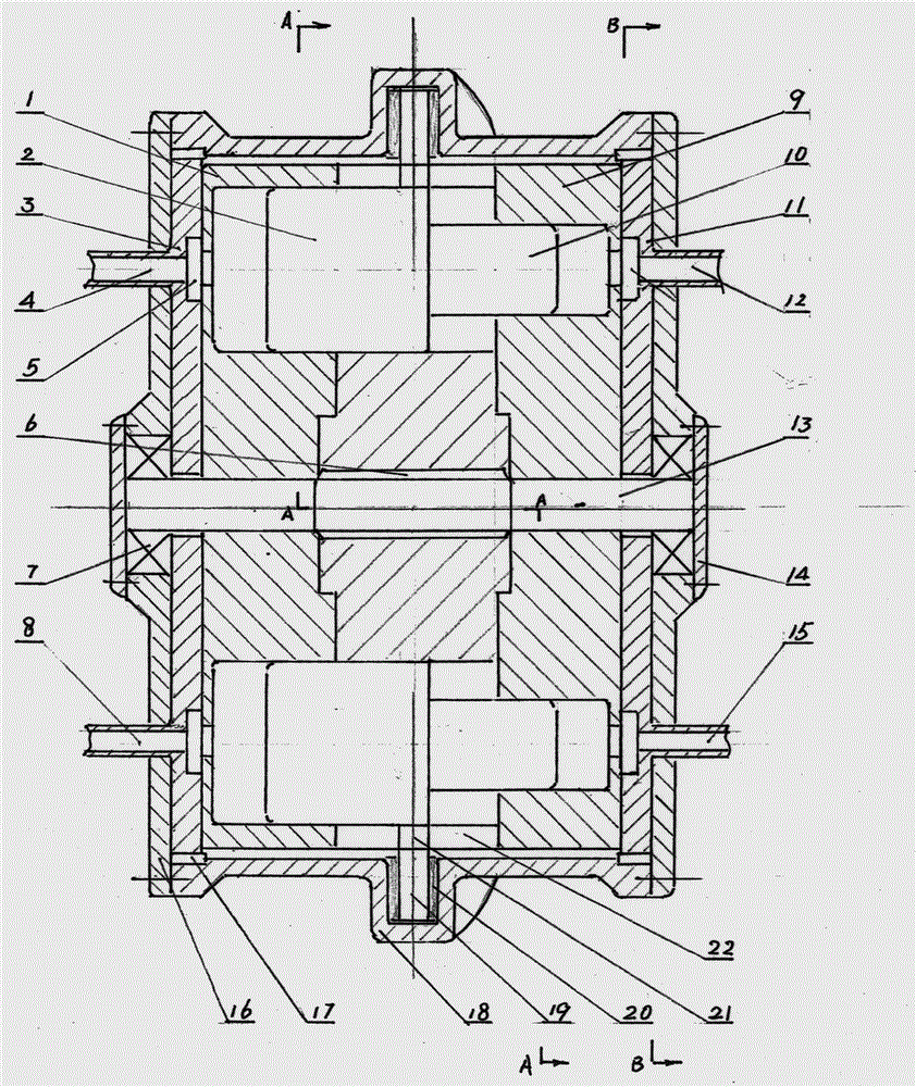
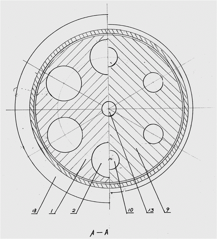
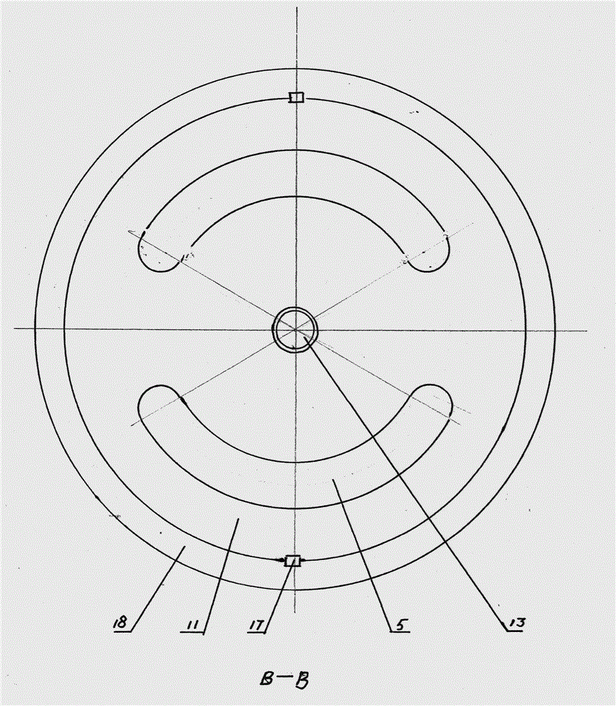
[0022] Figure 4 It is a schematic diagram of the working connection of the hydraulic transformer. The rectangle in the figure represents the hydraulic transformer. Its internal structure and working principle have been analyzed before, and now only its external connection is further identified. The hydraulic interface 4 and the hydraulic interface 8 form the input primary circuit. The interface 12 and the hydraulic interface 15 constitute the output secondary circuit, and the two circuits are isolated from each other, so that the oil will not be mixed. Connect hydraulic port 4 to a constant pressure source such as an energy storage tank, and hydraulic port 8 to return to the oil tank, while hydraulic port 12 and hydraulic port 15 are both closed by valves. At this time, there is no input or output, and the inside of the transformer does not rotate. Measuring the pressure of the primary circuit will be the constant pressure of the accumulator tank and the secondary circuit wil...
PUM
 Abstract
Description
Claims
Application Information
 - R&D
- Intellectual Property
- Life Sciences
- Materials
- Tech Scout
- Unparalleled Data Quality
- Higher Quality Content
- 60% Fewer Hallucinations
Browse by: Latest US Patents, China's latest patents, Technical Efficacy Thesaurus, Application Domain, Technology Topic, Popular Technical Reports.
© 2025 PatSnap. All rights reserved.Legal|Privacy policy|Modern Slavery Act Transparency Statement|Sitemap|About US| Contact US: help@patsnap.com


