Intermesh Engagement Device

一种接合装置、接合机构的技术,应用在相互啮合的离合器、动力装置、传动装置控制等方向,能够解决不能充分降低碰撞噪音、不能精确地控制移动构件速度等问题

Active Publication Date: 2015-12-23
TOYOTA JIDOSHA KK
View PDF4 Cites 11 Cited by
  • Summary
  • Abstract
  • Description
  • Claims
  • Application Information

AI Technical Summary

Problems solved by technology

With this structure, if the thrust is controlled based on the amount of stroke of the sleeve, there is a possibility that the impact noise cannot be sufficiently reduced because the speed of the moving member cannot be precisely controlled

Method used


Image

  • Intermesh Engagement Device
  • Intermesh Engagement Device
  • Intermesh Engagement Device

Examples


Embodiment Construction

[0028] Hereinafter, a mesh type engagement device according to an embodiment of the present invention will be described in detail with reference to the accompanying drawings. The present invention is not limited by the embodiments. Components in the embodiments described below also include components that can be easily conceived by those skilled in the art or substantially equivalent components.

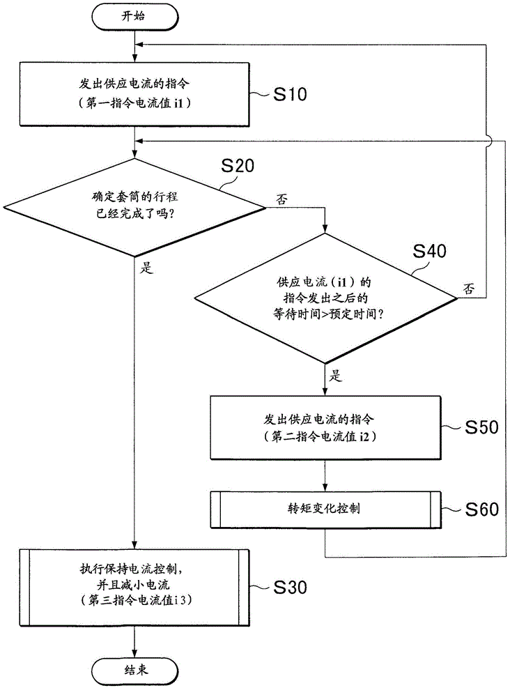
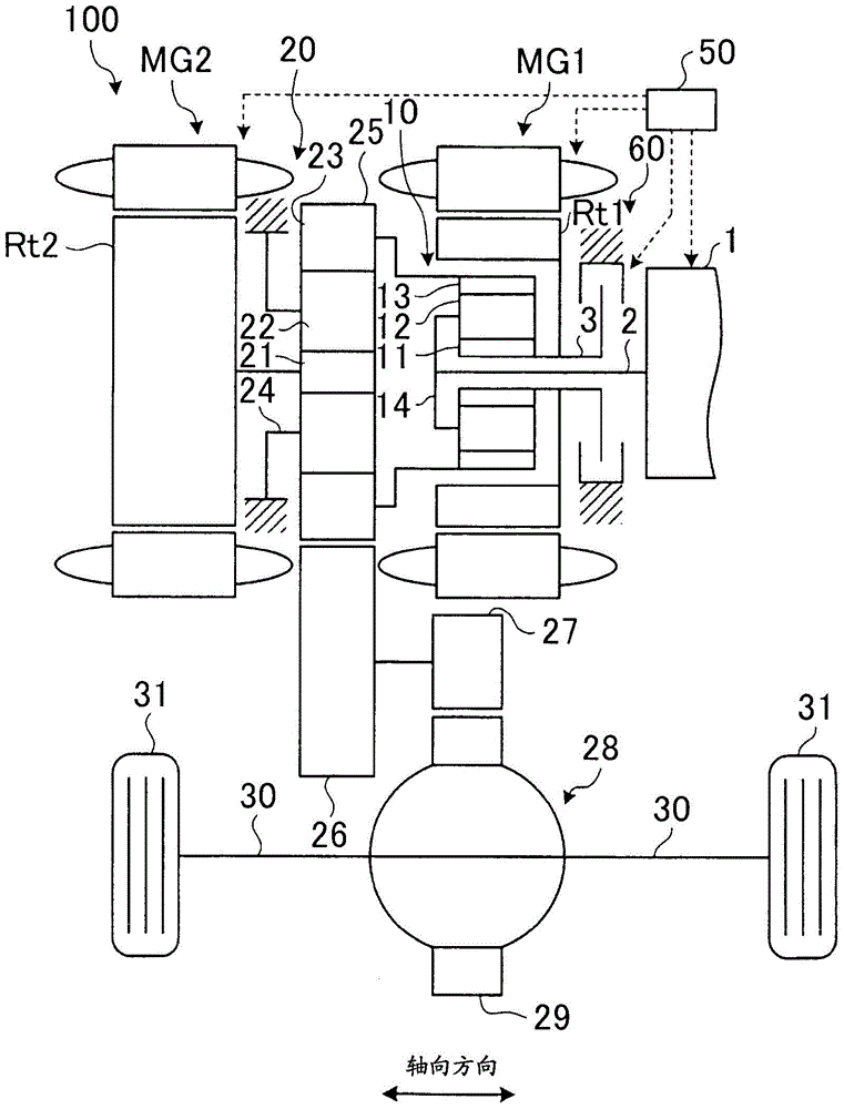
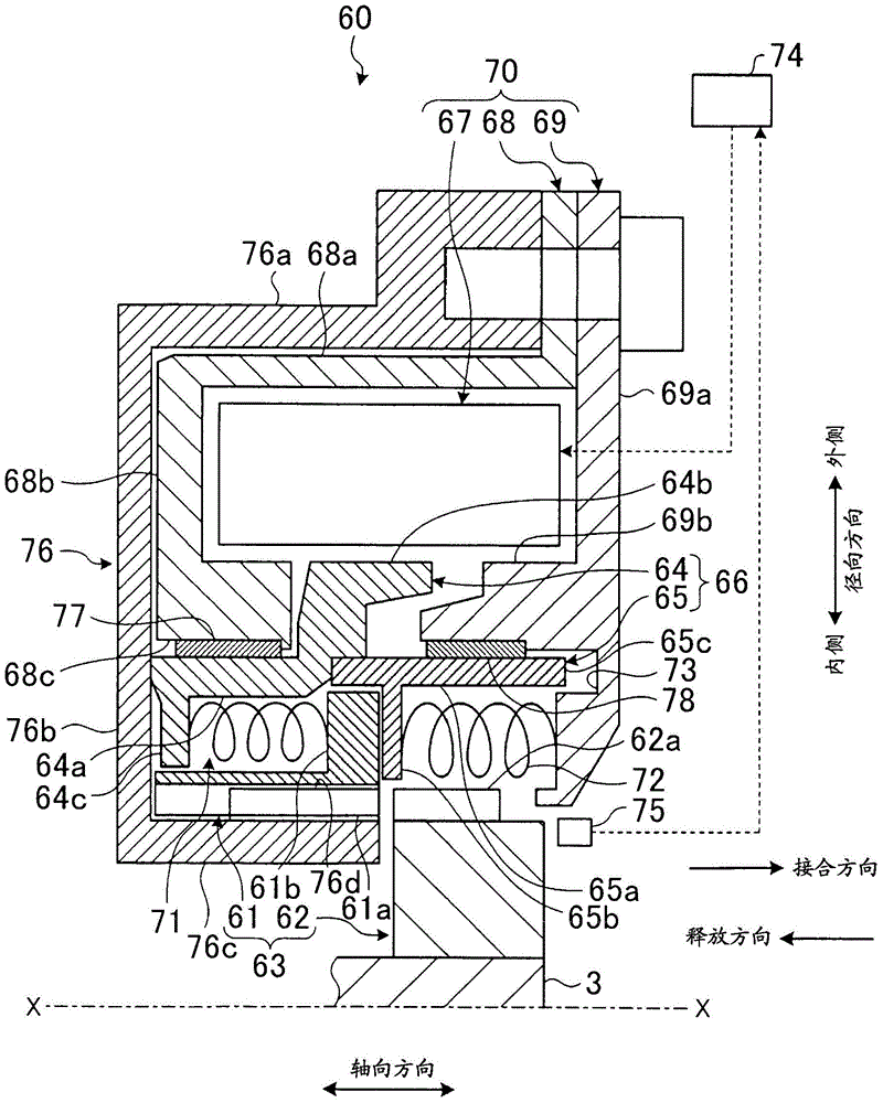
[0029] Below, refer to the figure to Figure 11 The first embodiment will be described. The present embodiment relates to a mesh type engaging device. figure 1 is a flowchart related to engagement control according to the first embodiment of the present invention. figure 2 is a schematic configuration diagram of the vehicle according to the first embodiment. image 3 is a cross-sectional view showing the mesh-type engaging device according to the first embodiment. Figure 4 is a side view showing the joint mechanism according to the first embodiment. Figure 5 It is a figure w...


PUM


Abstract

An intermesh engagement device includes an intennesh engagement mechanism, a moving member, an actuator configured to apply a thrust to a moving member in an engaging direction, a transmission spring configured to transmit the thrust of the actuator from the moving member to a sleeve, a return spring, a stopper, and an electronic control unit configured to control the actuator. The electronic control unit is configured to execute first control (S 10) for setting the thrust of the actuator to a thrust in a first region, and, when a halfway stopped state has occurred through the first control, execute second control (S50) for setting a thrust larger than the thrust in the first control. The first region is a range in which the thrust is larger than an urging force of the return spring and is smaller than the sum of the urging force of the return spring and a maximum urging force of the transmission spring.

Description

technical field [0001] The present invention relates to intermeshing engagement devices. Background technique [0002] There is an existing mesh engagement device. For example, Japanese Patent Application Publication No. 2010-25279 (JP 2010-25279A) describes a controller for an electromagnetic clutch. The controller includes first setting means and second setting means. When a pair of clutch parts is switched from a disengaged state to an engaged state, the first setting means sets a first driving current as an initial driving current for the electromagnetic actuator so that the The plunger is accelerated in one direction, and then the plunger is decelerated in the above-mentioned direction due to the elastic force corresponding to the stroke amount exceeding the driving force in response to the stroke amount. The second setting means, setting a second drive current that is a new drive current for the electromagnetic actuator so that after the plunger has been decelerated...

Claims


Application Information

Patent Timeline
Patent Type & Authority Applications(China)
IPC IPC(8): F16D48/06
CPCF16H2061/047B60K6/445F16D11/14F16D27/118B60K2006/381F16D2011/008F16D2500/3026F16D2500/70418F16D2500/7044B60K6/38B60K6/387F16D48/064F16D2500/1022F16D2500/10412F16D2500/50239F16D2500/70631Y02T10/62F16H61/02F16D2011/004F16D11/10F16D2500/10462
Inventor 江渊弘章舟桥真岩濑雄二加藤正太郎永井秀和桥本洋人
Owner TOYOTA JIDOSHA KK
Why Eureka
Try Eureka