Torsional vibration damper and control device for torsional vibration damper

a technology of torsional vibration and damper, which is applied in the direction of vibration dampers, vibration suppression adjustments, rotational vibration suppression, etc., can solve the problems of large collision noise and change in angular acceleration of rotary members, and achieve the damage of e.g., the inertia body and the rolling members can be limited, and the noise in the torsional vibration damper can be reduced.

Active Publication Date: 2021-05-27
TOYOTA JIDOSHA KK
View PDF0 Cites 4 Cited by
  • Summary
  • Abstract
  • Description
  • Claims
  • Application Information

AI Technical Summary

Benefits of technology

[0012]When the engine is stopped, the rotation of the rotary member is stopped, and the rolling masses and the inertia body drop gravitationally. As described, according to one aspect of the present disclosure, the rotary member is mounted on the output shaft in such a manner that none of the rolling masses is situated within the predetermined angle range of the rotary member in which the inertia body is to be supported by only one of the rolling masses situated swhen the engine is stopped. Otherwise, according to another aspect of the present disclosure, an angle of the output shaft is adjusted in such a manner that none of the rolling masses is situated within the predetermined angle range of the rotary member when the engine is stopped. In other words, according to the present disclosure, the inertia body is supported by a plurality of the rolling masses when the engine is stopped. For this reason, the inertia body will not be oscillated widely by vibrations and will not collide against the other members during propulsion in an electric vehicle mode. That is, noise in the torsional vibration damper can be reduced, and damages of e.g., the inertia body and the rolling members can be limited.

Problems solved by technology

However, the rotary member is vibrated inevitably by pulsation of the torque applied thereto, and consequently an angular acceleration of the rotary member is changed.
In this situation, the inertia body collide against the rotary member due to vibrations generated during propulsion, and consequently large collision noise is induced due to collision of the inertia body against the rotary member.

Method used


Image

  • Torsional vibration damper and control device for torsional vibration damper
  • Torsional vibration damper and control device for torsional vibration damper
  • Torsional vibration damper and control device for torsional vibration damper

Examples


first example

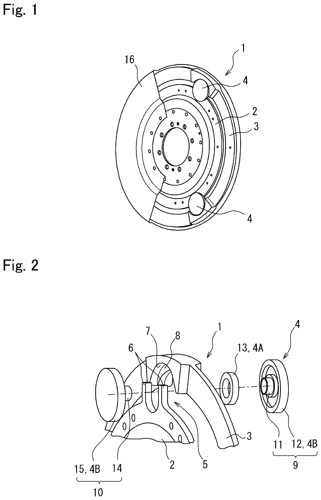
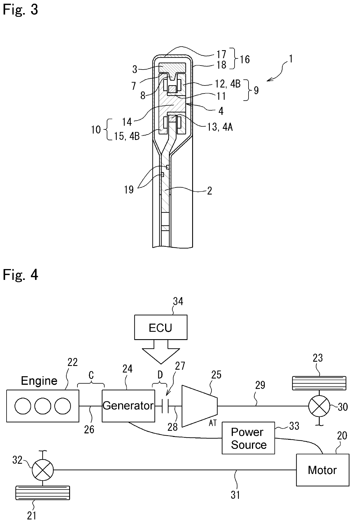
[0028]Here will be explained the first example of the present disclosure with reference to FIGS. 1 to 3. As illustrated in FIG. 1, the torsional vibration damper 1 comprises: a rotary member 2 that is rotated by a torque applied thereto; an inertia body 3 as a mass arranged coaxially and concentrically with the rotary member 2; and a plurality of rolling mass 4 connecting the rotary member 2 to the inertia body 3 to transmit torque applied to the rotary member 2 to the inertia body 3. According to the first example shown in FIG. 1, total three rolling mass 4 are interposed between the rotary member 2 and the inertia body 3.

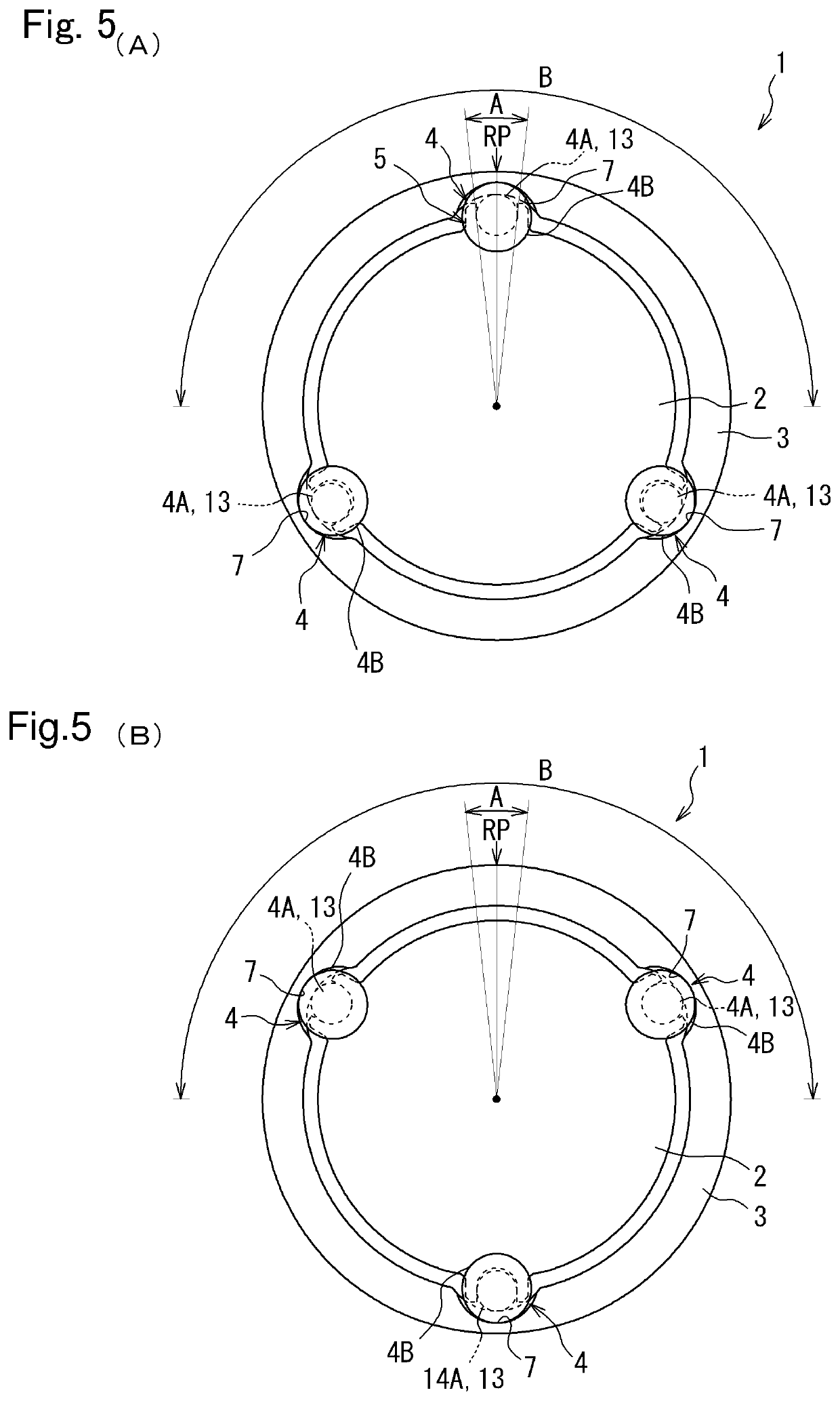
[0029]The rotary member 2 is mounted on an output shaft of the engine or a shaft connected to the output shaft of the engine (neither of which are shown) to be rotated integrally therewith. In order to startup the engine smoothly, the output shaft of the engine is sopped within a predetermined angular range when the engine is stopped. That is, the engine is stoppe...

second example

[0052]Turning to FIG. 2, there is shown the torsional vibration damper 1 according to the second example of the present disclosure. According to the second example, a ring-shaped buffer member 35 made of e.g., synthetic resin is attached to an outer circumferential edge of the rotary member 2 to absorb a collision impact of the inertia body 3. The buffer member 35 comprises a contact surface 36 covering the outer circumferential edge of the rotary member 2. Specifically, a curvature of the contact surface 36 is substantially identical to a curvature of the inner circumferential surface of the inertia body 3, and the inner circumferential surface of the inertia body 3 dropping gravitationally comes into contact to the contact surface 36. According to the second example, a clearance between the contact surface 36 of the buffer member 35 and the inner circumferential surface of the inertia body 3 is set such that the inner circumferential surface of the inertia body 3 will not come int...

third example

[0055]Turning to FIG. 10, there is shown the torsional vibration damper 1 according to the third example of the present disclosure. According to the third example, five rolling masses 4 re arranged in the torsional vibration damper 1. Accordingly, five retainers 5 are formed on the circumference of the rotary member 2 at regular intervals, and the rolling mass 4 is held in each of the retainers 5. Likewise, five raceway surfaces 7 are formed on the inner circumference of the inertia body 3 at regular intervals. The remaining structure of the torsional vibration damper 1 according to the third example is identical to that of the first example, and detailed explanations for the common structure will be omitted.

[0056]If the rotary member 2 according to the third example is stopped at an angle shown in FIG. 11 as a result of stopping the engine 22, one of the rolling masses 4 situated within the predetermined range A drops gravitationally and the diametrically smaller section 4A thereof...


PUM


Abstract

A torsional vibration damper that can reduce collision noise of an inertia body when a rotary member is stopped, and a control device therefore. In the torsional vibration damper, a rotary member is mounted on an output shaft of an engine such that none of rolling masses is situated within a predetermined angle range above a rotational center axis of the rotary member when the engine is stopped. Therefore, when the engine is stopped, the inertia body will not be supported by only one of the rolling masses situated within the predetermined angle range.

Description

CROSS REFERENCE TO RELATED APPLICATION[0001]The present disclosure claims the benefit of Japanese Patent Application No. 2019-214382 filed on Nov. 27, 2019 with the Japanese Patent Office, the disclosure of which is incorporated herein by reference in its entirety.BACKGROUNDField of the Disclosure[0002]Embodiments of the present disclosure relate to the art of a torsional vibration damper for damping torsional vibrations resulting from pulsation of torque by an oscillating motion of an inertia mass, and a control device for controlling the torsional vibration damper. Especially, the embodiments of the present disclosure relate to a torsional vibration damper mounted on a vehicle that can be propelled while stopping an engine, and a control device for controlling the torsional vibration damper.Discussion of the Related Art[0003]JP-A-2019-100498 describes an example of a torsional vibration damper. The torsional vibration damper taught by JP-A-2019-100498 comprises: a rotary member ro...

Claims


Application Information

Patent Timeline
Patent Type & Authority Applications(United States)
IPC IPC(8): F16F15/14F16F15/00
CPCF16F15/145F16F15/002F16F2236/08F16F2232/02F16F2230/18F16F2222/08F16F15/14F16F15/26F16F15/1457
Inventor NAKAMURA, TAIKINISHIDA, HIDEYUKIISHIBASHI, MASAYUKI
Owner TOYOTA JIDOSHA KK
Why Eureka
Try Eureka