Starting Device for Engines

a technology of starting device and engine, which is applied in the direction of electric generator control, magnetic body, electric control, etc., can solve the problems of noise problem generated around streets, noise problem of loud collision noise, and increase in noise generated at the time of starting the engine (generated noise), so as to reduce the noise of gears and reduce collision noise. , the effect of improving the wear resistance of pinion gears

Active Publication Date: 2012-05-17
DENSO CORP
View PDF0 Cites 4 Cited by
  • Summary
  • Abstract
  • Description
  • Claims
  • Application Information

AI Technical Summary

Benefits of technology

[0036]The other object of the present invention is to provide a starting device for engines that has an electromagnetic switch that can reduce a collision noise generated when a movable iron core collides with a fixed iron core.
[0037]The other object of the present invention is to provide a starting device for engines that can reduce the gear noise generated when the pinion gear collides and engages to the ring gear, and the starter that can improve the wear resistance of the pinion gear.
[0042]In addition, since the solenoid device and the electromagnetic switch share the magnetic plate, number of the parts can be reduced, and thus lowers the manufacturing cost.

Problems solved by technology

When the above-mentioned electromagnetic switch is operated, that is, energizing the electromagnetic coil magnetizes the fixed iron core, the movable iron core made of soft steel collides the base part made of soft steel so that a loud collision noise occurs.
Moreover, if the number of the vehicles equipped with the idol stop system increases, the number of the case where many vehicles start the engines all at once on the public streets under traffic congestion will increase, therefore the noise generated at the time of starting the engines (generated noise) increases, and noise problem generated around streets is assumed.
With this composition, since a size increases in two directions in a radical direction to a main axis of the motor, a big disadvantage on the sizes arise in respect of installing the starter to the engine.
However, since the electromagnetic switch and the electromagnetic means are arranged parallel in the circumferential direction of the motor in the starter disclosed in the above-mentioned Publication No. 56-42437, avoiding interference with other parts in two directions in the radical direction to the main axis of the motor seems to have many difficulties.
Among these, noises generated at the time of starting in the starter are a gear engagement noise that is generated when the pinion gear engages to the ring gear provided on the engine side, and an operation noise of the electromagnetic switch.
Since the operation noise of the electromagnetic switch is the noise generated at the moment of turning on the electromagnetic switch, i.e., the collision noise generated when the movable iron core collides with the fixed iron core is the loudest.
However, when the gears disclosed in the Publication No. 49-27140 and the Publication No. 59-65665 are used as the pinion gear, since the gears shown in both publications are the laminated objects, it is possible to reduce the gear engagement noise, but the effect of reducing the gear end surface collision noise is not expectable.
In this structure, since each metal plate (especially tooth part) that constitute the pinion gear cannot be bent mutually at the time the pinion gear collides with the ring gear when the gear shown in the Publication No. 49-27140 is used as the pinion gear with, it is difficult to reduce gear end surface collision noise.
For this reason, even when the gear shown in the Publication No. 59-65665 is used as the pinion gear like the case of the Publication No. 49-27140, it is difficult to reduce the gear end surface collision noise generated when the pinion gear collides with the ring gear.

Method used


Image

  • Starting Device for Engines
  • Starting Device for Engines
  • Starting Device for Engines

Examples


first embodiment

The First Embodiment, the Second Example

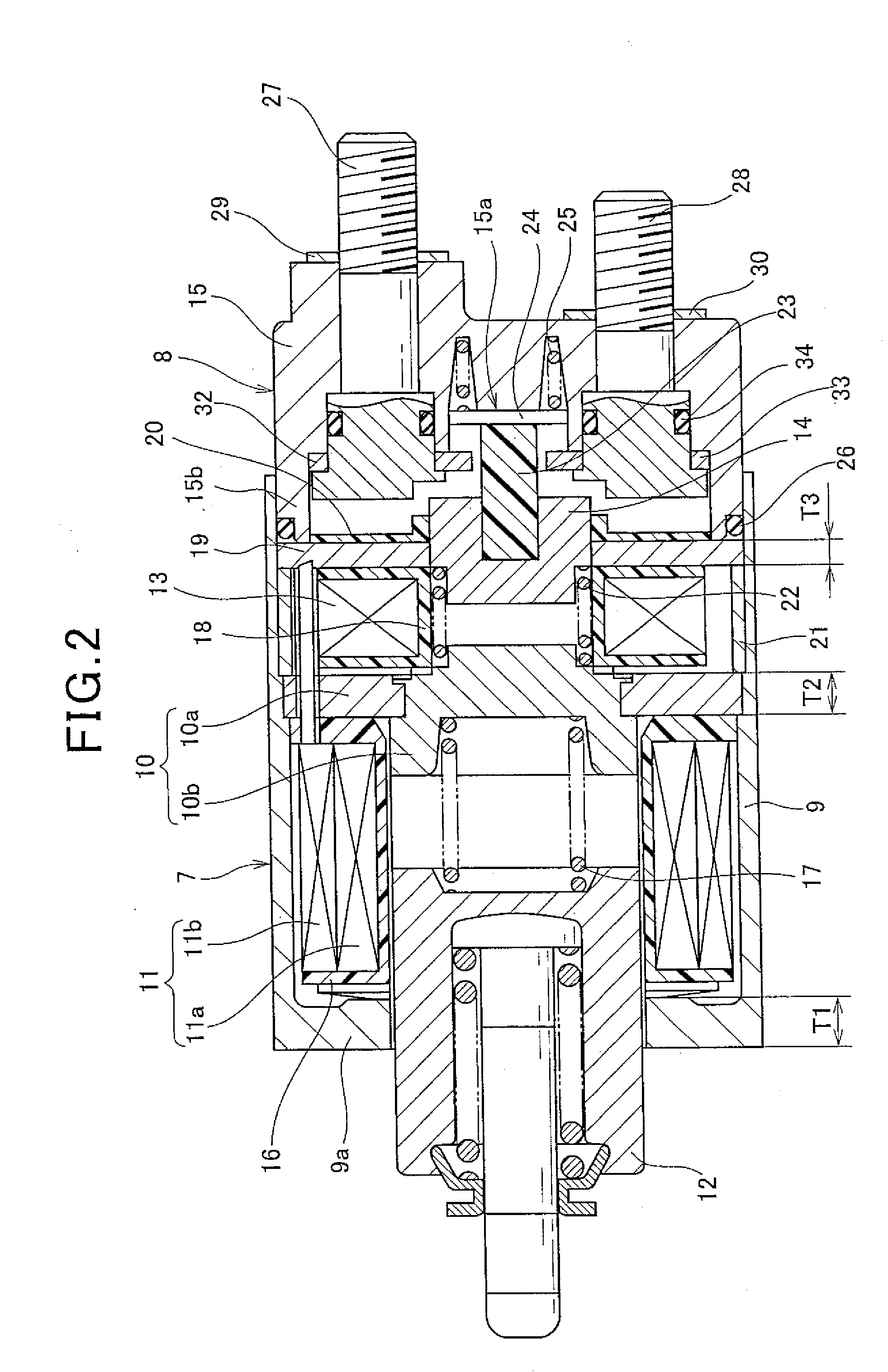
[0110]In the electromagnetic switch unit disclosed in the first example, the second example is characterized that when a thickness of the bottom wall portion 9a of the unit case 9 is T1, a thickness of the magnetic plate 10a is T2, and a thickness of the second magnetic plate 19 is T3, as shown in FIG. 2, the following formula (1) is satisfied.

T2≦T1+T3   (formula 1)

[0111]For example, at the time of designing the magnetic circuit of the solenoid device 7, the thickness of the magnetic plate 10a must be secured when a quantity of magnetic flux increases most, i.e., when the plunger 12 is attracted to the core part 10b so that the magnetic plate 10a may not carry out magnetic saturation.

[0112]In other words, it is a usual state to form the magnetic plate 10a thin enough not to carry out magnetic saturation. By the way, if the first coil 11 and the second coil 13 are wound so that the direction of the magnetic flux generated by energization to the...

second embodiment

The Second Embodiment, the third Example

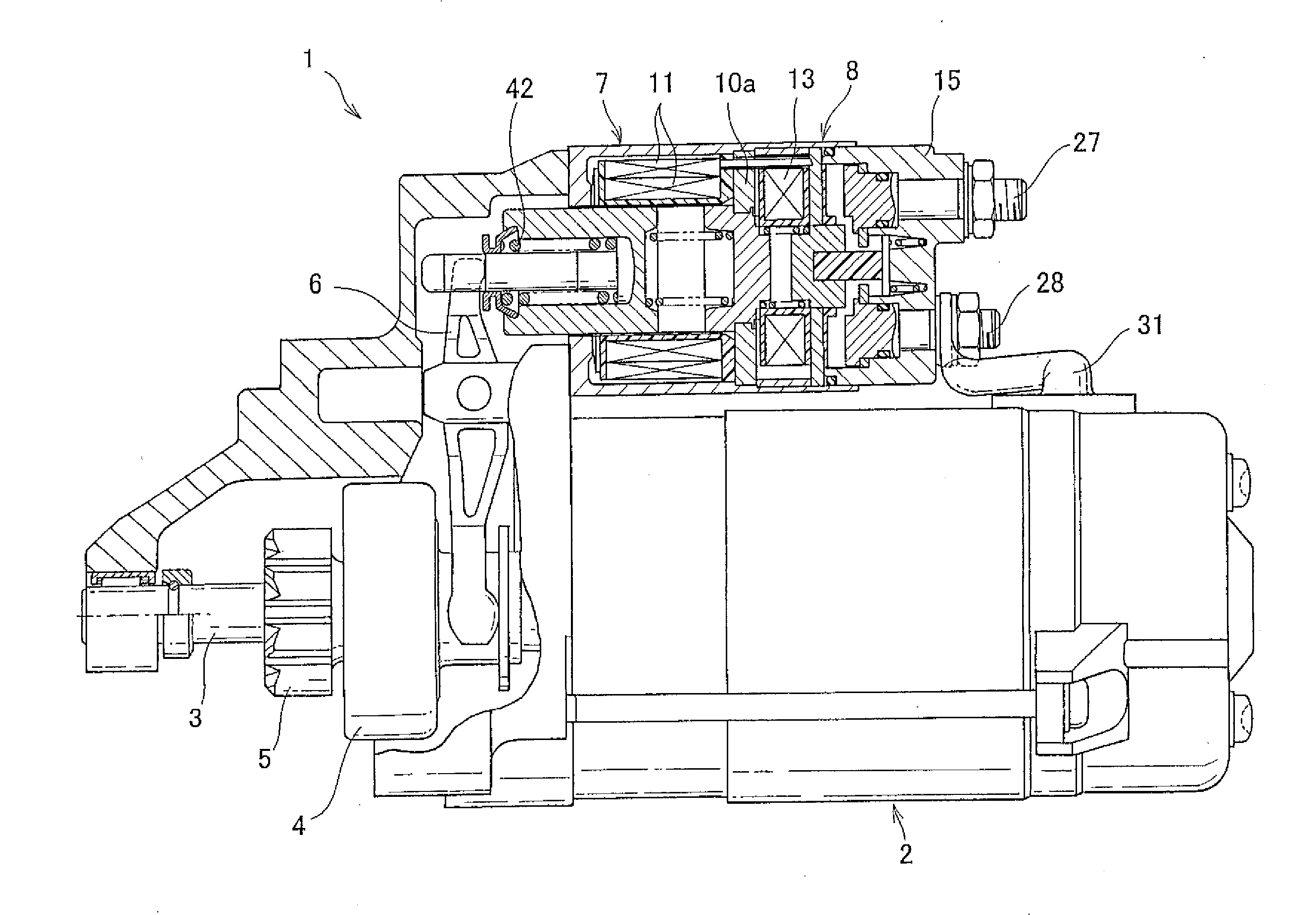
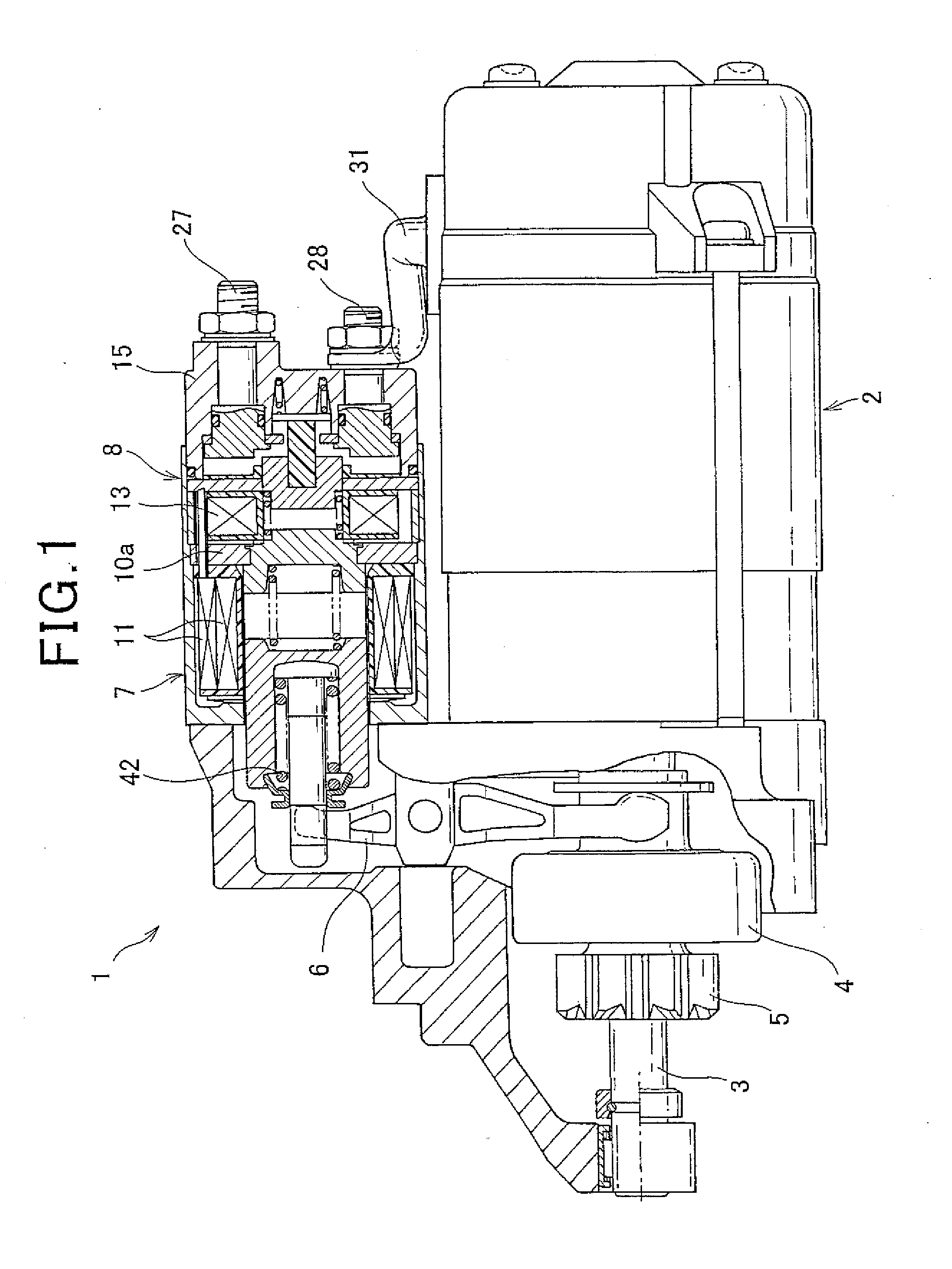
[0155]FIG. 8 is a sectional view of the electromagnetic switch 100 according to the second embodiment, the third example. The electromagnetic switch 100 of the second embodiment, the third example is constituted to use a separate electromagnetic coil and a movable iron core for the movement of pushing out the pinion gear 5 to the ring gear 41 side of the engine via the shift lever 6, and the movement of intermitting the energization current to the motor 2.

[0156]Specifically, the electromagnetic switch 100 comprises the electromagnetic coil 11 and the movable iron core 12 for pushing out the pinion gear 5 to the ring gear 41 side of the engine, a second electromagnetic coil 13 and a second movable iron core 14 for intermitting the energization current to the motor 2, and the fixed iron core 10 shared by both movements.

[0157]It should be appreciated that the same reference numbers are given to the same elements as the first example, and explanat...

third embodiment

The Third Embodiment, the third Example

[0217]FIG. 15 is a plane view of the pinion gear 200 according to the third embodiment, the third example of the present invention.

[0218]The pinion gear 200 of the third example is integrated in such a manner that the steel sheets 65 are laminated and joined in the axial direction by welding etc, which is the same manner as in the first example of the third embodiment. In addition, as shown in FIG. 7, oils and fats 64 such as grease is filled in the concave portions 65d formed in the first sheet 65A.

[0219]When the pinion gear 200 rotates, the oils and fats 64 filled in the concave portions 65d moves little by little from the gap between the laminated steels 65 to the outer circumference side by the centrifugal force. Most of the fat and oil which has reached the outer circumference seeps little by little. Since the seeping oil acts as lubricating oil between teeth which engage with the ring gear 41, wear resistance of the pinion gear 200 and th...


PUM


Abstract

An electromagnetic switch unit comprises a solenoid device that pushes out a pinion gear to a ring gear side of an engine, and an electromagnetic switch that opens and closes a main point of contact of a motor circuit. The solenoid device and the electromagnetic switch are arranged in series in an axial direction, while a magnetic plate that forms a part of magnetic circuit between a first coil used for the solenoid device and a second coil used for the electromagnetic switch is shared by the solenoid device and the electromagnetic switch.

Description

CROSS-REFERENCE TO RELATED APPLICATIONS [0001]This is a Continuation of U.S. patent application Ser. No. 12 / 461,327 filed Aug. 7, 2009. The disclosure of this prior application is incorporated herein by reference in its entirety.[0002]This application is based on and claims the benefit of priority from earlier Japanese Patent Application No. 2008-204222 filed Aug. 7, 2008, No. 2008-231128 filed Sep. 9, 2008, and No. 2008-320617 filed Dec. 17, 2008, the contents of which are incorporated herein by reference.BACKGROUND OF THE INVENTION[0003]1. Technical Field of the Invention[0004]The present invention relates to a starting device for engines having an electromagnetic switch that opens and closes a main point of contact of a motor circuit and a solenoid device that pushes a pinion gear to an engine side.[0005]2. Description of the Related Art[0006]As conventional technology, a starting device for engines disclosed in Japanese Utility Model Application Laid-Open Publication No. 56-4243...

Claims


Application Information

Patent Timeline
Patent Type & Authority Applications(United States)
IPC IPC(8): F02N11/00
CPCF02D2041/2079F02N11/087F02N15/022F02N15/023F02N15/063F02N15/067Y10T74/132H01F7/1607H01F7/1833H01F2007/1692H01H51/065Y10T74/131H01F7/088H02K7/14
Inventor MURATA, MITSUHIRONIIMI, MASAMI
Owner DENSO CORP
Why Eureka
Try Eureka