Wind scooper and wind outlet device with wind scooper and passenger car

A technology of air outlet device and air guide hood, which is applied in vehicle parts, transportation and packaging, heating/cooling equipment, etc. The best air outlet effect and the effect of increasing the air outlet speed

Active Publication Date: 2015-12-23
ZHENGZHOU YUTONG BUS CO LTD
View PDF8 Cites 3 Cited by
  • Summary
  • Abstract
  • Description
  • Claims
  • Application Information

AI Technical Summary

Problems solved by technology

[0002] The main air duct of a passenger car is generally long. Due to the high air velocity in the main air duct, according to Bernoulli's principle, the pressure is low when the air velocity is high. The air outlet speed of the air outlet in the high-speed area is very low
[0003] like figure 1 As shown, the existing passenger car air outlet device includes an air outlet arranged on the lower side of the main air duct along the incoming flow direction, and the air outlet includes a circular first air outlet 5 and a second air outlet 6 arranged in sequence from front to back , due to the high airflow velocity in the main air duct, the lateral pressure of the airflow is low, and no flow diversion measures are taken, only very little airflow flows out from the air outlet, and the air outlet effect is not good
This air outlet device is used on large passenger cars or small and medium passenger cars with air conditioners located at both ends of the vehicle. Since the wind speed in the air duct is relatively high in the area close to the air conditioner, this will cause the wind speed at the air outlet near the air conditioner to be lower than that far away from the air conditioner. , and this phenomenon will become more serious with the lengthening of the air-conditioning duct
If no diversion measures are taken, the wind speed at the air outlet away from the air conditioner may be several times that of the air outlet near the air conditioner, which will lead to uneven temperature inside the car and affect the passenger experience

Method used


Image

  • Wind scooper and wind outlet device with wind scooper and passenger car
  • Wind scooper and wind outlet device with wind scooper and passenger car
  • Wind scooper and wind outlet device with wind scooper and passenger car

Examples


Embodiment Construction

[0027] Embodiments of the present invention will be further described below in conjunction with the accompanying drawings.

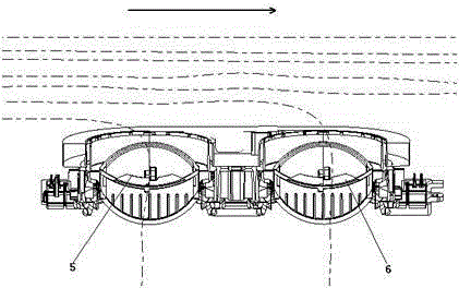
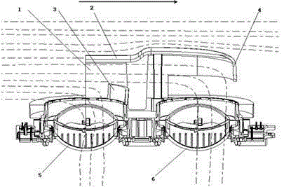
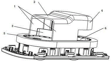
[0028] Embodiment 1 of the passenger car of the present invention, the passenger car comprises a main air duct and an air outlet device, such as Figure 2 to Figure 6 As shown, the air outlet device includes air outlets arranged on the lower side of the main air duct from front to back along the incoming flow direction of the air flow. The air outlets include circular first air outlets 5 and second air outlets 6. There are slots around the air outlet, and an air guide cover is installed above the air outlet. The air guide cover includes two left and right side panels 1 opposite to each other and a top panel 2 connecting the tops of the two side panels 1. Insert the side panels 1 into the slots. The installation of the air guide cover is realized in the middle, the two side plates 1 and the top plate 2 are surrounded to form an air guide channel extending...


PUM


Abstract

The invention relates to a wind scooper and a wind outlet device with the wind scooper and a passenger car. The wind scooper comprises two oppositely-arranged side plates and a top plate connecting the tops of the two side plates. A wind guide channel extending in the front-back direction is defined by the two side plates and the top plate. The wind guide channel comprises a front-end opening where airflow is allowed to enter. Wind deflectors for guiding airflow to automobile wind flue wind outlets are arranged between the two side plates. When the number of the wind deflectors is two or more, the wind deflectors are distributed in the wind guide channel at intervals in a front-back manner; a front-back penetrating wind passing hole is formed in the upstream wind deflector at least; and according to the two adjacent wind deflectors, the rear wind deflector on the back stage at least partially covers the wind passing hole in the front wind defector on the front stage in the vertical direction. Due to the blocking and drainage effect of the wind deflectors, airflow is made to be turned and flow out of the wind outlets, and the wind outlet speed of the wind outlets is greatly increased; wind outflows from a main wind flue uniformly on the whole, stepwise flow division and drainage are achieved, wind can outflow rapidly and synchronously through the multiple corresponding wind outlets, and the main wind flue achieves the better wind outlet effect.

Description

technical field [0001] The invention relates to a wind guide cover, an air outlet device equipped with the wind guide cover and a passenger car. Background technique [0002] The main air duct of a passenger car is generally long. Due to the high air velocity in the main air duct, according to Bernoulli's principle, the pressure is low when the air velocity is high. The air outlet speed of the air outlet in the high-speed area is very low. [0003] Such as figure 1 As shown, the existing passenger car air outlet device includes an air outlet arranged on the lower side of the main air duct along the incoming flow direction, and the air outlet includes a circular first air outlet 5 and a second air outlet 6 arranged in sequence from front to back , due to the high air velocity of the main air duct, the low lateral pressure of the air flow, and no flow diversion measures, only very little air flow flows out from the air outlet, and the air outlet effect is not good. This air...

Claims


Application Information

Patent Timeline
Patent Type & Authority Applications(China)
IPC IPC(8): F24F13/08B60H1/00
CPCB60H1/00B60H2001/00092F24F13/08
Inventor 刘积成田杰安郭永升齐祥军李雅雷
Owner ZHENGZHOU YUTONG BUS CO LTD
Why Eureka
Try Eureka