Stator core, motor and motor making production method

A stator core and stator technology, which is applied in the manufacture of motor generators, electrical components, electromechanical devices, etc., can solve the problems of small effective contact area, low production efficiency, and complicated process, so as to simplify the production process and improve the production efficiency. , The effect of high winding speed

Active Publication Date: 2012-07-11
GREE ELECTRIC APPLIANCES INC +2
View PDF3 Cites 10 Cited by
  • Summary
  • Abstract
  • Description
  • Claims
  • Application Information

AI Technical Summary

Problems solved by technology

This solution can achieve the purpose of reducing material costs and improving winding efficiency, but the inline tooth-shaped units 1 are connected by thin bridges 2, which need to be bent and shaped into a circle. During the bending process, the thin bridges 2. The part is easy to break and will be deformed outside the main plane after bending. In order to reduce the unevenness of the stator core sheets caused by the interference after deformation, it is necessary to wash away part of the material within the bending range, such as forming a circular arc part 3 , so that this part has a gap after bending to make the effective contact area smaller and increase the magnetic flux leakage, and after bending into a circle, the last connecting part must be welded, or the pressure-holding tooling should be used to keep it from falling apart. Thereby the process is cumbersome and the production efficiency is low

Method used


Image

  • Stator core, motor and motor making production method
  • Stator core, motor and motor making production method
  • Stator core, motor and motor making production method

Examples


no. 1 example

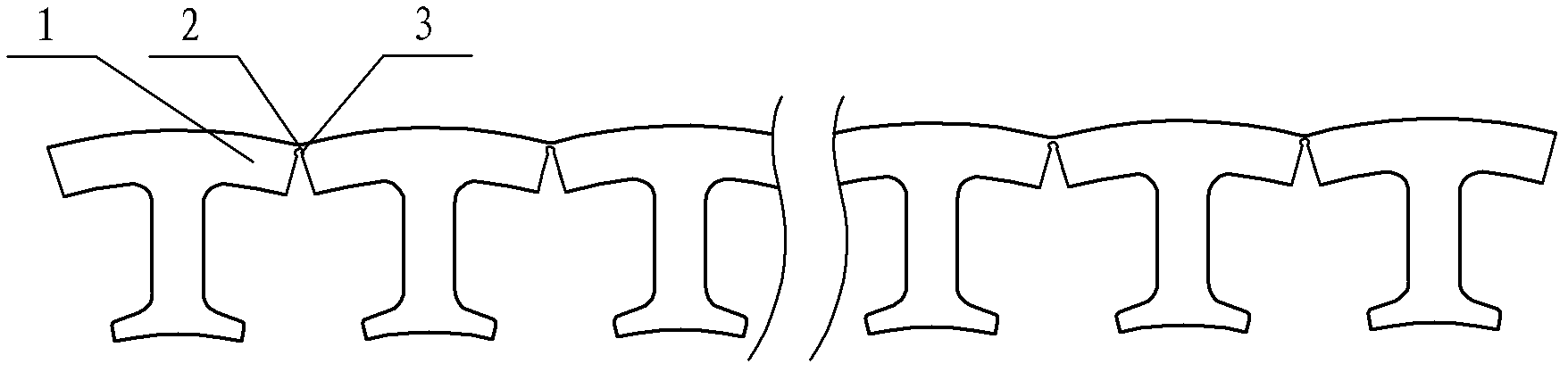
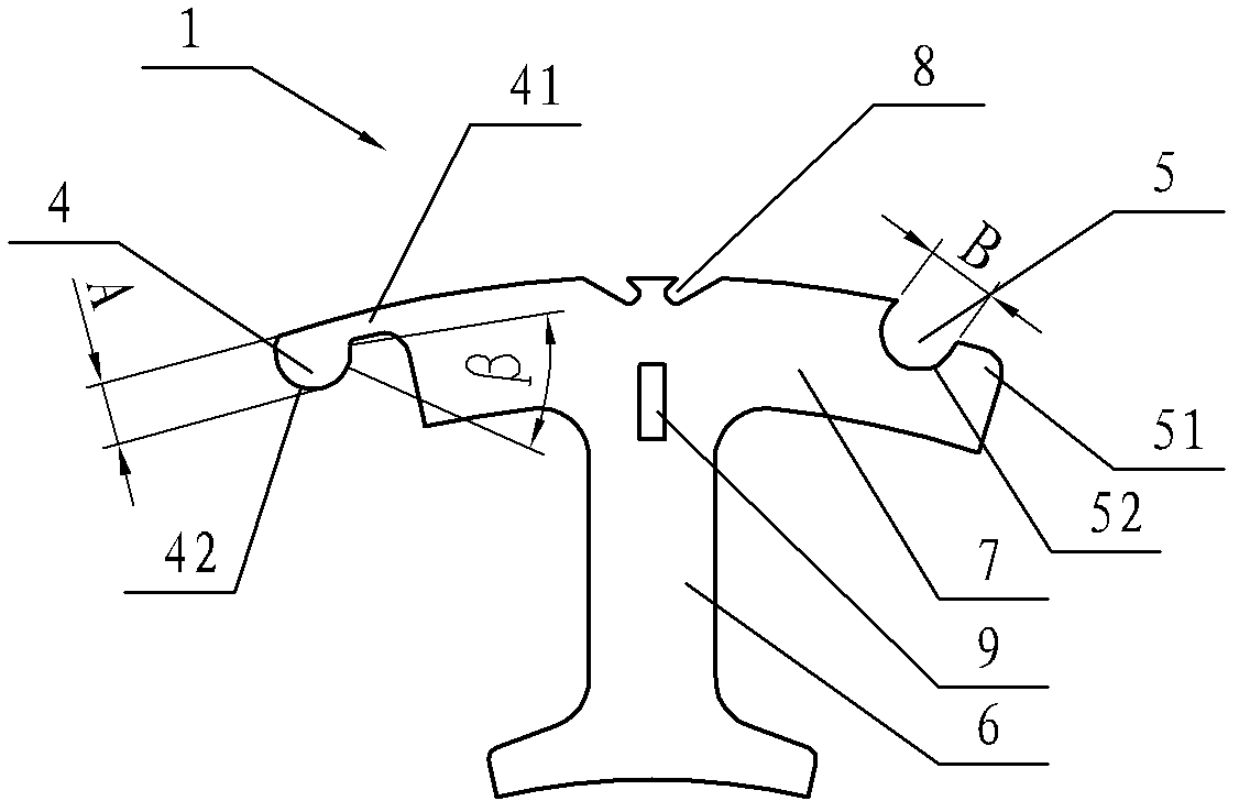
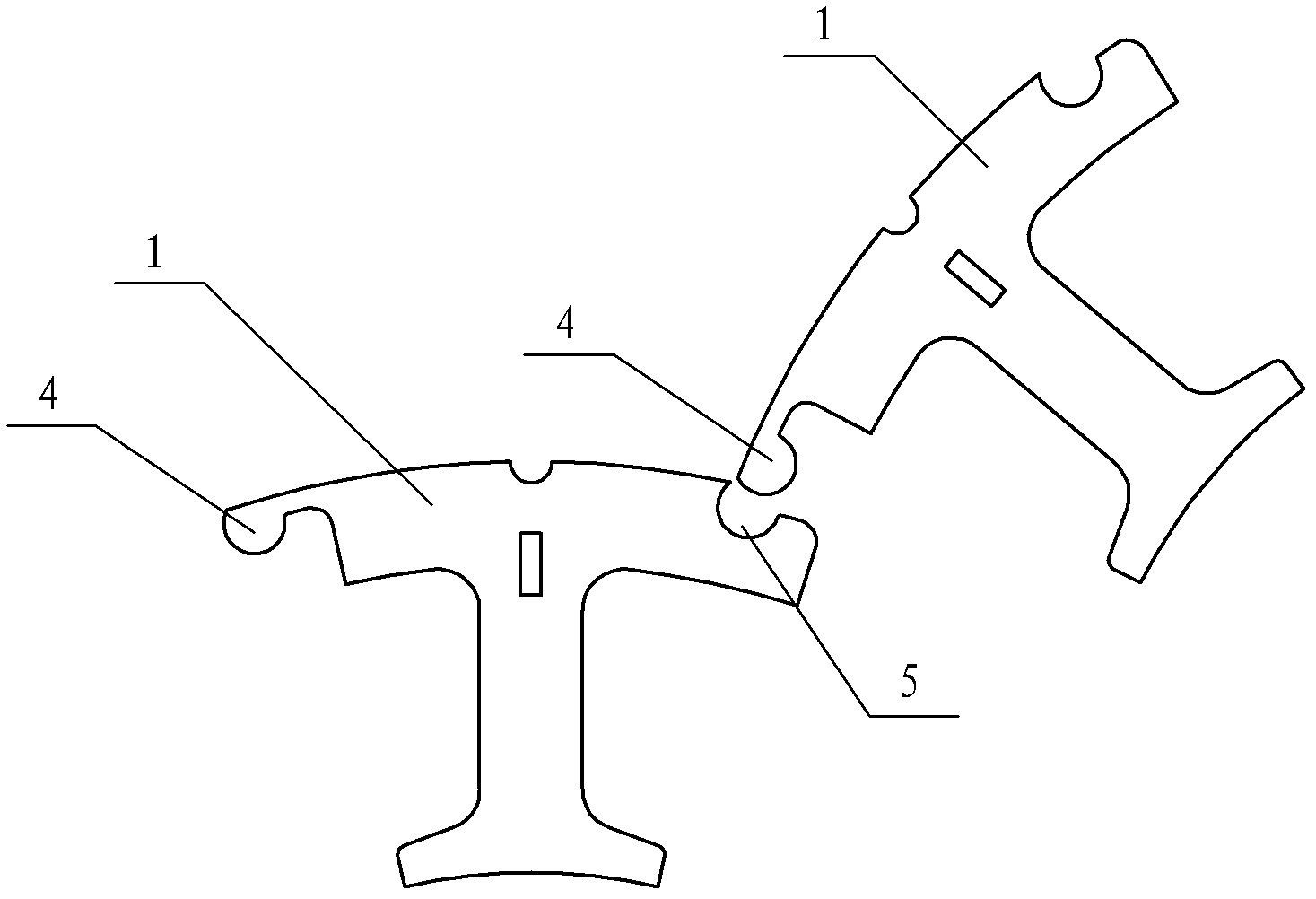
[0028] The stator core is formed by assembling a plurality of tooth-shaped units 1 in the circumferential direction. Each tooth-shaped unit 1 is formed by stacking a certain number of tooth-shaped unit sheets, which has a certain thickness. figure 2 is the plane view of toothed unit 1, and each piece of toothed unit has figure 2 the shape shown. Such as figure 2 As shown, the tooth-shaped unit 1 includes a tooth part 6 for winding, one end of which is provided with a stopper for preventing the coil from slipping, and the other end is a yoke part 7 forming the outer circumference of the stator core, and the winding slots are separated from the teeth. The left and right sides of part 2. The side of the yoke 7 of the tooth-shaped unit 1 away from the tooth is provided with a positioning groove 8 as a positioning part. The shape of the positioning groove 8 can be freely set according to needs, such as dovetail, trapezoid, triangle, arc, etc., as long as it can realize The po...


PUM


Abstract

The invention aims at providing a stator core which is formed by serrated units buckled mutually and needs no pressure holding or welding. The stator core provided by the invention comprises a plurality of serrated units assembled together in a circumferential direction, each serrated unit is provided with a teeth part used for twisting wire and a yoke part positioned at one end of the teeth part, a circular arc bulge is arranged at one end of the yoke part, a groove matched with the bulge in shape is arranged on the other end of the yoke part, and one serrated unit is matched with the groove of an adjacent serrated unit by the bulge, so as to form a planar hinge capable of rotating relatively between two adjacent serrated units.

Description

technical field [0001] The invention relates to the field of motors, in particular to a stator core used in a motor stator, a motor with the stator core and a manufacturing method of the motor. Background technique [0002] A motor is an electromagnetic device that converts or transmits electrical energy according to the law of electromagnetic induction, including a stator and a rotor. The stator includes a winding composed of an iron core and a coil, wherein the coil is wound at the winding slot of the iron core through an opening on the iron core. The traditional manufacturing method of the stator is to first punch out circular punches with a mold, then stack the circular punches to form an iron core, and then use a special inner winding machine to wind the coil. This method has low material utilization rate and high cost, and the mold is relatively complex and the stamping efficiency is low. In addition, coil winding requires special equipment and the winding speed is lo...

Claims


Application Information

Patent Timeline
Patent Type & Authority Applications(China)
IPC IPC(8): H02K1/14H02K15/00
Inventor 张之元
Owner GREE ELECTRIC APPLIANCES INC
Why Eureka
Try Eureka