
A motion compensation method for bistatic forward-looking sar

A motion compensation and bistatic technology, which is applied in the radar field, can solve the problems of data block reduction and processing efficiency, etc., and achieve the effects of fast speed, accurate compensation and focusing, and high compensation accuracy

Active Publication Date: 2017-09-26
UNIV OF ELECTRONICS SCI & TECH OF CHINA
View PDF1 Cites 0 Cited by
  • Summary
  • Abstract
  • Description
  • Claims
  • Application Information

AI Technical Summary

Problems solved by technology

However, this method is only suitable for situations where the azimuth range does not change much, and the data block also reduces the processing efficiency

Method used


Image

  • A motion compensation method for bistatic forward-looking sar
  • A motion compensation method for bistatic forward-looking sar
  • A motion compensation method for bistatic forward-looking sar

Examples


Embodiment Construction

[0055] In order to describe content of the present invention conveniently, at first the following terms are explained:

[0056] Term 1: Bistatic forward-looking SAR (bistatic forward-looking SAR)

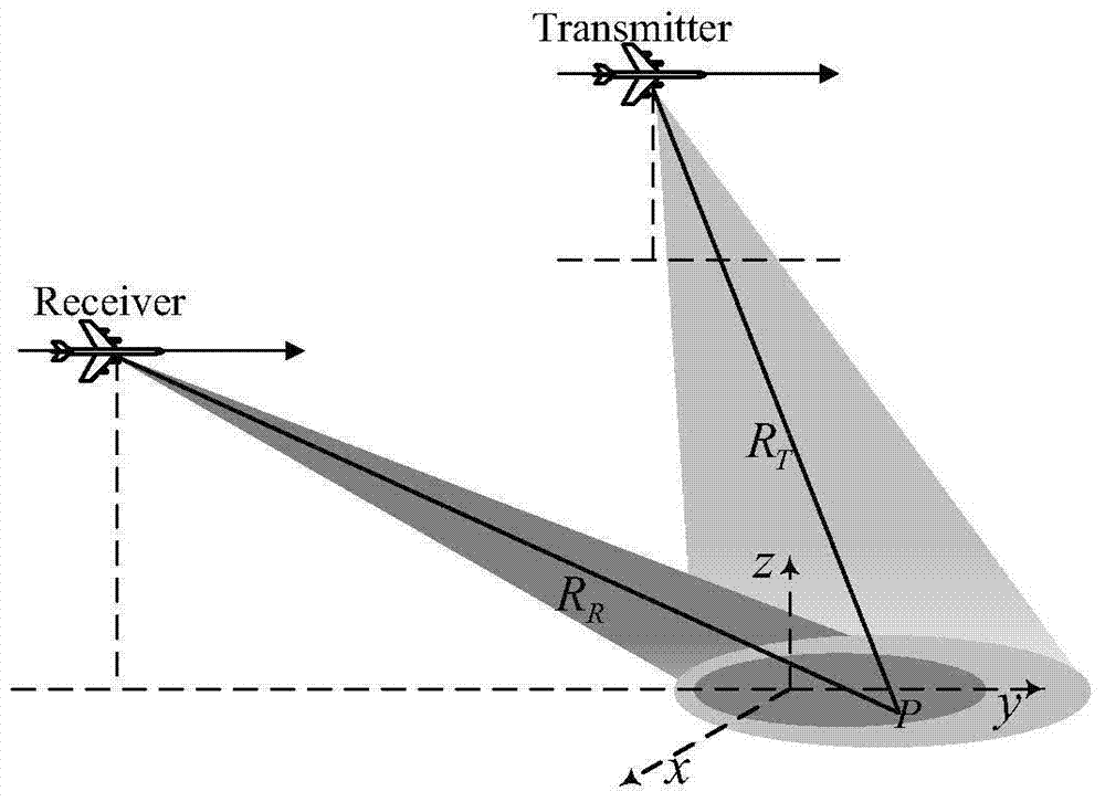
[0057] Bistatic forward-looking SAR refers to a SAR system in which the transmitting station and receiving station of the system are placed on different platforms, and the receiving station images the area directly in front of it. At least one of the platforms is a moving platform, which is conceptually a bistatic radar.

[0058] Term 2: Motion Error Azimuth Spatial Variation

[0059] The space-variation of motion error and azimuth means that targets at different azimuth positions in the same range gate have different motion error compensation functions.

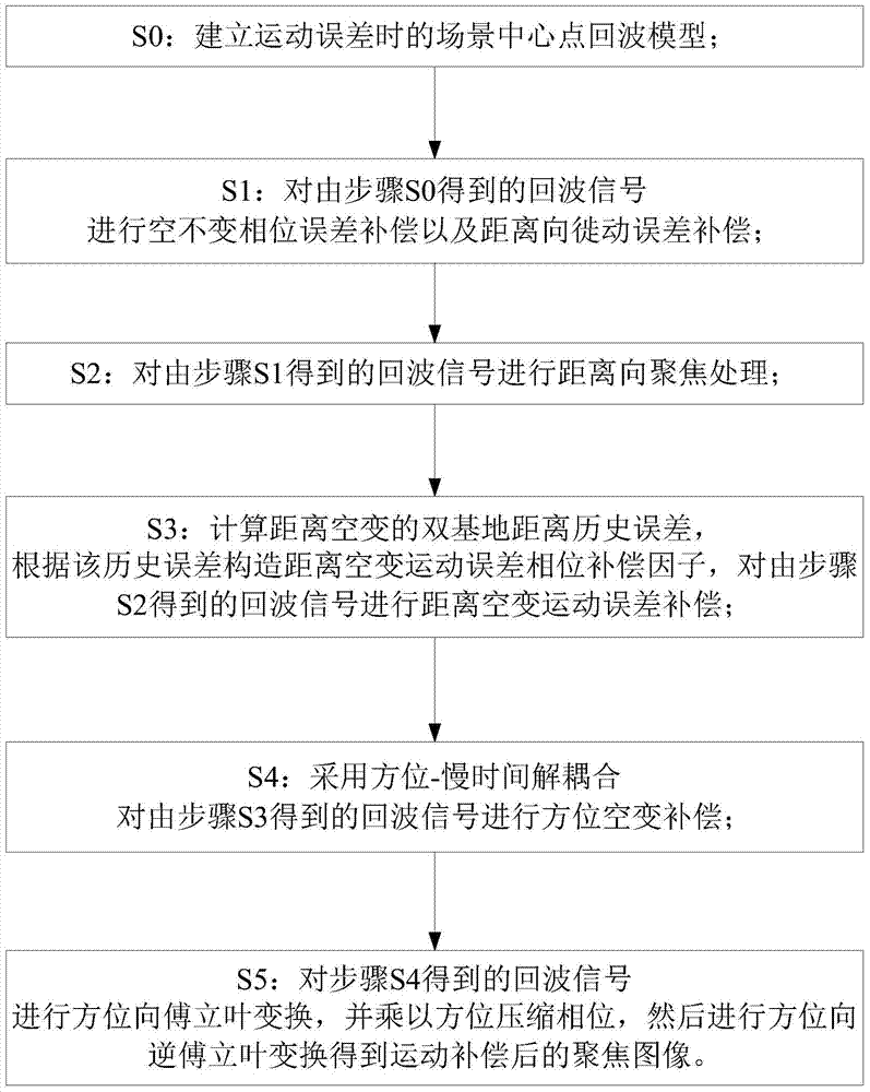
[0060] like figure 1 Shown is the method flowchart of the present invention, a kind of bistatic forward-looking SAR motion compensation method of the present invention, mainly comprises the following steps:

[0061] S0: The ech...


PUM


Abstract

The invention discloses a bistatic forward-looking SAR motion compensation method, which adopts the azimuth-slow time decoupling operation to separate and process different azimuth point targets in the same range unit, and the main steps include: (1) space-invariant motion error Compensation; (2) Range-oriented focusing processing; (3) Range space-varying motion error compensation; (4) Azimuth space-varying motion error compensation; (5) Azimuth compression; overcoming traditional synthetic aperture radar motion compensation methods and existing bistatic The synthetic aperture radar motion compensation method is difficult to correct the azimuth space variation of the motion error; the method of the invention can effectively remove the azimuth space variation of the motion error, thereby realizing the accurate compensation and focusing of the bistatic forward-looking synthetic aperture radar.

Description

technical field [0001] The invention belongs to the field of radar technology, in particular to a motion compensation method in a bistatic forward-looking synthetic aperture radar (SAR). Background technique [0002] Synthetic Aperture Radar (SAR) is an all-time, all-weather high-resolution microwave remote sensing imaging radar. SAR has played an increasingly important role in the fields of military reconnaissance, topographic mapping, ocean and hydrological observation, environmental and disaster monitoring, resource exploration, and detection of crustal changes. However, in the forward-looking area of ​​the aircraft, because the traditional monostatic SAR cannot form the orthogonality between the equidistance line and the iso-Doppler line, and there is a Doppler ambiguity problem, it does not have the forward-looking imaging capability in mechanism. [0003] The bistatic forward-looking SAR adopts the working mode of transmitting and receiving separately, which can form ...

Claims


Application Information

Patent Timeline
Patent Type & Authority Patents(China)
IPC IPC(8): G01S13/90
CPCG01S13/90G01S13/9043G01S13/9019G01S13/9058
Inventor 武俊杰蒲巍黄钰林李文超杨建宇杨海光杨晓波
Owner UNIV OF ELECTRONICS SCI & TECH OF CHINA
Learn More