Continuous spectrum signal target automatic detection method based on single vector subsurface buoy

An automatic detection and continuum technology, applied in measuring devices, sound wave re-radiation, radio wave measurement systems, etc., can solve the problems of difficult determination of detection threshold and susceptibility to interference

Active Publication Date: 2015-12-23
HARBIN ENG UNIV
View PDF5 Cites 11 Cited by
  • Summary
  • Abstract
  • Description
  • Claims
  • Application Information

AI Technical Summary

Problems solved by technology

[0007] The purpose of the present invention is to provide a method for automatic detection of targets based on single-vector latent targets ba

Method used


Image

  • Continuous spectrum signal target automatic detection method based on single vector subsurface buoy
  • Continuous spectrum signal target automatic detection method based on single vector subsurface buoy
  • Continuous spectrum signal target automatic detection method based on single vector subsurface buoy

Examples


specific Embodiment approach 1

[0038] Specific implementation mode 1: A method for realizing automatic detection of a continuum signal target based on a single-vector latent target in this embodiment is implemented in the following steps:

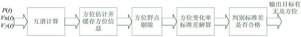
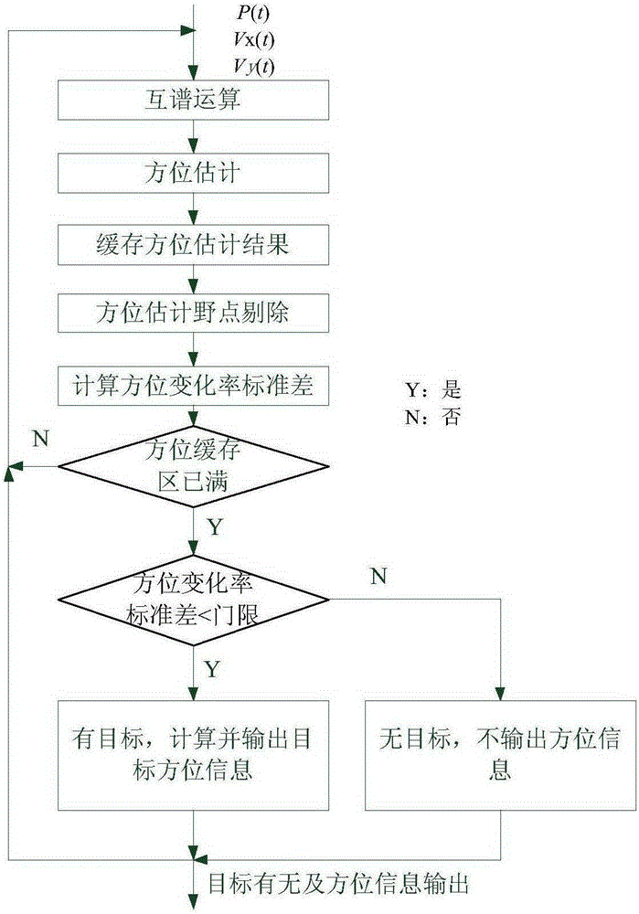
[0039] 1. Take the vector hydrophone sound pressure channel signal P(t), the x-axis vibration velocity Vx(t) and the y-axis vibration velocity Vy(t), respectively divide P(t) and Vx(t), P(t) Perform cross-spectrum calculation with Vy(t) to obtain the sound intensity flow spectrum I of the sound pressure channel signal P(t) and the x-axis vibration velocity Vx(t) and y-axis vibration velocity Vy(t) x (f) and I y (f), according to the sound intensity flow spectrum I x (f) and I y (f) Obtain the horizontal azimuth angle estimation result θ(f) of each frequency;

[0040] 2. Use the cross-spectrum histogram statistical method to estimate the continuum target azimuth, and obtain the current continuum signal target azimuth information θ 0 (n), and the continuum signal targe...

specific Embodiment approach 2

[0059] Specific embodiment two: the difference between this embodiment and specific embodiment one is: the method described in step one gives the horizontal azimuth angle estimation result θ(f) of each frequency according to the sound intensity flow spectrum, specifically:

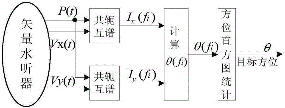
[0060] (1) The sound pressure channel signal P(t) and the x-axis vibration velocity channel signal Vx(t) and the y-axis vibration velocity channel signal Vy(t) perform cross-spectrum calculations to obtain two cross-spectrum outputs Its calculation formula is:

[0061] S P V x ( f ) = P ( f ...

specific Embodiment approach 3

[0068] 3. Specific implementation mode three: the difference between this implementation mode and specific implementation mode one or two is that step two is specifically:

[0069] (1) From formula (3), it can be seen that the orientation estimated by the cross-spectrum operation is related to the frequency f, so for each frequency point f i The expression for orientation estimation is written as:

[0070] θ ( f i ) = tg - 1 I y ( f i ) I x ( f i ) - - ...


PUM


Abstract

The invention provides a continuous spectrum signal target automatic detection method based on a single vector subsurface buoy. Firstly, a vector hydrophone sound pressure channel signal P(t) is taken, and cross-spectrum operation is carried out on the P(t), a Vx(t) and a Vy(t); secondly, a cross-spectrum histogram statistical method is used for continuous spectrum target bearing estimation; thirdly, jump points in a bearing cache array theta(n) are rejected, and bearing points with a stable measurement value are kept; fourthly, the bearing cache array theta(n) after the jump points are rejected in the third step is used for calculating a bearing change rate array delta theta(n), and a bearing change rate standard difference thetastd is further solved; and fifthly, a threshold thetastdDT for the bearing change rate standard difference is set, and whether the bearing change rate standard difference meets a threshold requirement is judged. The method of the invention is applied to a signal processing field, and the problems that the detection threshold is hard to determine in the existing energy detection method, and an energy detection method is easily disturbed can be solved.

Description

technical field [0001] The invention relates to an underwater acoustic signal detection method, in particular to an automatic detection method of a continuum signal target based on a single vector submerged mark. Background technique [0002] The vector hydrophone can measure the sound pressure and the three orthogonal components of the particle velocity at one point of the sound field at the same time and at the same point in space. Its vector channel has directivity independent of frequency, compared with the traditional sound pressure hydrophone In other words, the vector hydrophone can provide more sound field information and provide a larger choice for subsequent signal processing. In addition, joint information processing using vibration velocity and sound pressure can improve the detection performance of the signal and also improve the accuracy of signal parameter estimation. Because of the above reasons, vector hydrophones have received more and more attention in re...

Claims


Application Information

Patent Timeline
IPC IPC(8): G01S15/04G01S7/52
CPCG01S7/52G01S15/04
Inventor 吕云飞陈晓孙大军张迪王志宇
Owner HARBIN ENG UNIV
Why Eureka
Try Eureka