Exhaust hood

A technology of exhaust hood and exhaust pipe, applied in the field of exhaust hood, can solve the problems of incomplete gas discharge, reduced work efficiency, long operation time, etc., and achieve the effect of being beneficial to physical health and improving work efficiency

Active Publication Date: 2009-06-03
SEMICON MFG INT (SHANGHAI) CORP +1
View PDF3 Cites 0 Cited by
  • Summary
  • Abstract
  • Description
  • Claims
  • Application Information

AI Technical Summary

Problems solved by technology

Since more than 30 exhausts must be carried out, of course, the cleaning operation time will be prolonged and the work efficiency will be reduced.
[0004] Moreover, even after more than 30 N 2 After flushing, it may sometimes cause false alarms from the detectors (not shown) on the machine; this is because the detectors were originally designed to detect fluorine and other harmful gases that are harmful to the human body when they exceed the standard and give an alarm. , but in the actual operation process, some solvents used in the closed reaction chamber will also produce some non-toxic gases. After the gas reaches a certain concentration, it will also cause the alarm of the detector, while the existing technology only uses N 2 Flushing is easy to make the gas discharge incomplete. When this situation causes the alarm of the detector, the operator will mistakenly believe that the fluorine exceeds the standard, and the top cover of the sealed reaction chamber has to be closed again for N 2 flushing, so that the operation is at a standstill, resulting in unnecessary waste; but from the perspective of safety, the design of the detector cannot be cancelled.
[0005] In summary, there are two disadvantages in the exhaust device of the prior art: one is the N 2 The number of times of flushing and discharging makes the operation time long and the efficiency is low; secondly, due to the incomplete exhaust, it is easy to cause false alarm of the detector and affect the production

Method used


Image

  • Exhaust hood
  • Exhaust hood
  • Exhaust hood

Examples


Embodiment 1

[0019] Embodiment 1: exhaust hood 1000

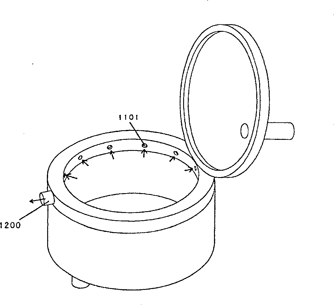
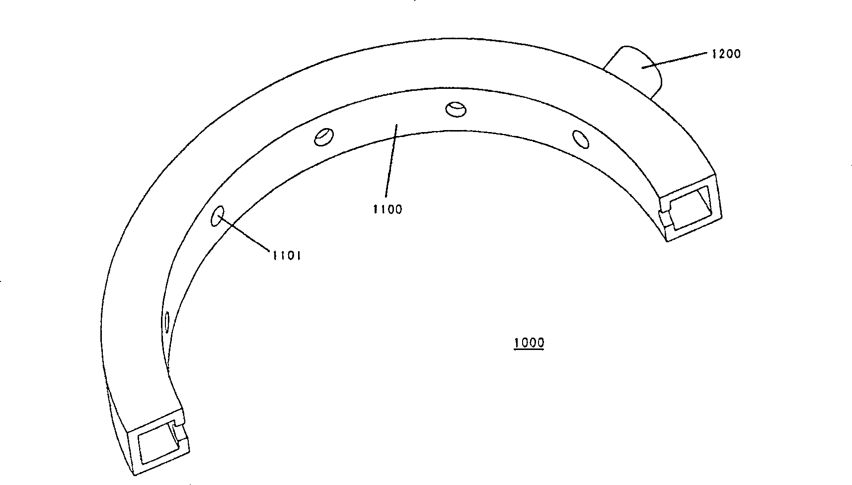
[0020] image 3 It is one of the embodiments of the present invention: a schematic diagram of an exhaust hood 1000 installed around the opening of the reaction chamber; the exhaust hood 1000 is a surrounding type exhaust hood, Figure 4 It is a structural schematic diagram of the exhaust hood 1000. It should be noted that the opening and closing of the reaction chamber top cover is not affected after the exhaust hood 1000 is installed; Figure 4 As shown, the exhaust hood 1000 installed in the present invention is a circumferential hollow sleeve 1100 and a pipeline 1200 communicated with the circumferential hollow sleeve 1100, and the inner wall of the hollow sleeve 1100 is provided with There are a plurality of exhaust holes 1101, and the pipeline 1200 is connected with a vacuum suction device (not shown in the figure), image 3 The direction indicated by the arrow in the figure is the direction in which the harmful gas is drawn out ...

Embodiment 2

[0023] Embodiment 2: Exhaust device

[0024] In order to strengthen the vacuum suction effect of the exhaust gas in the reaction chamber, the present invention also provides another embodiment: that is, on the basis of the first embodiment above, a vertical exhaust ( EXHAUST) tube 1300, such as Figure 5 Shown is the structural representation of embodiment two, and an exhaust hood 1000 adds an exhaust pipe 1300 to form the structural representation of the exhaust device; The exhaust pipe 1300 is connected with a vacuum suction device (not shown), when the When the exhaust pipe 1300 is started together with the exhaust hood 1000, since the exhaust pipe 1300 can directly discharge the waste gas that rises to the central position above the opening of the closed reaction chamber, the exhaust hood 1000 is mainly responsible for removing the waste gas from the closed reaction chamber. Exhaust air is exhausted around the opening, thus making the exhaust effect more pronounced.

...

Embodiment 3

[0026] Embodiment Three: Exhaust Equipment

[0027] On the basis of the above embodiments, in order to achieve the purpose of reducing equipment costs, another embodiment of the present invention can also be derived, such as Figure 6It is a structural schematic diagram of the third embodiment of the present invention: the exhaust equipment contains a plurality of exhaust devices 2000 as described in the second embodiment, and the exhaust equipment is suitable for work sites with multiple closed reaction chambers, wherein each reaction chamber The hollow casing 1100 of the exhaust hood 1000 of the chamber is placed around the opening of the closed reaction chamber, and each exhaust pipe 1300 is arranged above the opening of the closed reaction chamber; the plurality of exhaust pipes 1300 are collected into a general After the exhaust pipe 3100, the total exhaust pipe 3100 is connected with a vacuum suction device (not shown).


PUM


Abstract

One kind of fume hood, encircle set around the airtight reaction chamber aperture to collect and discharges the waste gas, including: A center spatial drive pipe, and the pipeline which is connected with this center spatial drive pipe unites,another end of this pipeline connects with the vacuum de-aerating plant,equip at least air vent on the endophragm of this center spatial drive pipe ; the airtight reaction chamber waste gas is pumped from air vent the center spatial drive pipe and is discharged from the pipeline; Place above this installment fixes the exhaust pipe on the upper of the stated airtight reaction chamber open mouth,to strengthen the exhaust effect; Moreover, it also may gather many airtight reaction chambers fume hood exhaust pipe into an always pipeline, connects with the vacuum pumps installment; Because this equipment may exhaust while cleans,it does not need to wait for 30time of above N2flushes then to be able to clean like the existed the technology, therefore enables the working efficiency remarkably to enhance; And is more advantageous to operator's health.

Description

technical field [0001] The invention relates to the technical field of integrated circuit manufacturing, in particular to an exhaust hood for collecting and discharging waste gas generated in a closed reaction chamber (Chamber). Background technique [0002] In the manufacturing process of integrated circuits, in order to ensure the normal operation of the machine and reduce the number of downtime (DOWN) to a minimum, regular preventive maintenance (preventive maintenance) must be carried out on the machine including the closed reaction chamber. , PM), because this kind of maintenance now generally uses fluorine-containing gases, such as: C 4 f 8 、C 5 f 8 etc., so it is easy to produce harmful gas residues. When the staff maintain the machine, these fluorine-containing gases will endanger their health; moreover, the organic solvent PF5060 used in the closed reaction chamber is also a volatile fluorine-containing gas. Therefore, detectors are generally installed on the ma...

Claims


Application Information

Patent Timeline
Patent Type & Authority Patents(China)
IPC IPC(8): B08B15/04
Inventor 郑富源孙虎
Owner SEMICON MFG INT (SHANGHAI) CORP
Why Eureka
Try Eureka