Lens-free microscope based on LED light source and image reconstruction method of microscope

An LED light source, image reconstruction technology, applied in microscopes, optics, optical components, etc., can solve the problems of cumbersome laser light source, reduce system volume and cost, and achieve the effect of simplifying system structure, reducing cost, and reducing volume

Active Publication Date: 2015-12-23
NANJING UNIV OF SCI & TECH
View PDF4 Cites 22 Cited by
  • Summary
  • Abstract
  • Description
  • Claims
  • Application Information

AI Technical Summary

Problems solved by technology

Although this method omits the imaging lens, it introduces an additional expensive and bulky laser light source, which does not effectively reduce the size and cost of the system
In addition, the harsh requirements of the interferometry itself on the measurement environment, as well as the speckle noise introduced by the highly coherent light source also show that it is not an ideal way to achieve lensless microscopic imaging

Method used


Image

  • Lens-free microscope based on LED light source and image reconstruction method of microscope
  • Lens-free microscope based on LED light source and image reconstruction method of microscope
  • Lens-free microscope based on LED light source and image reconstruction method of microscope

Examples


Embodiment Construction

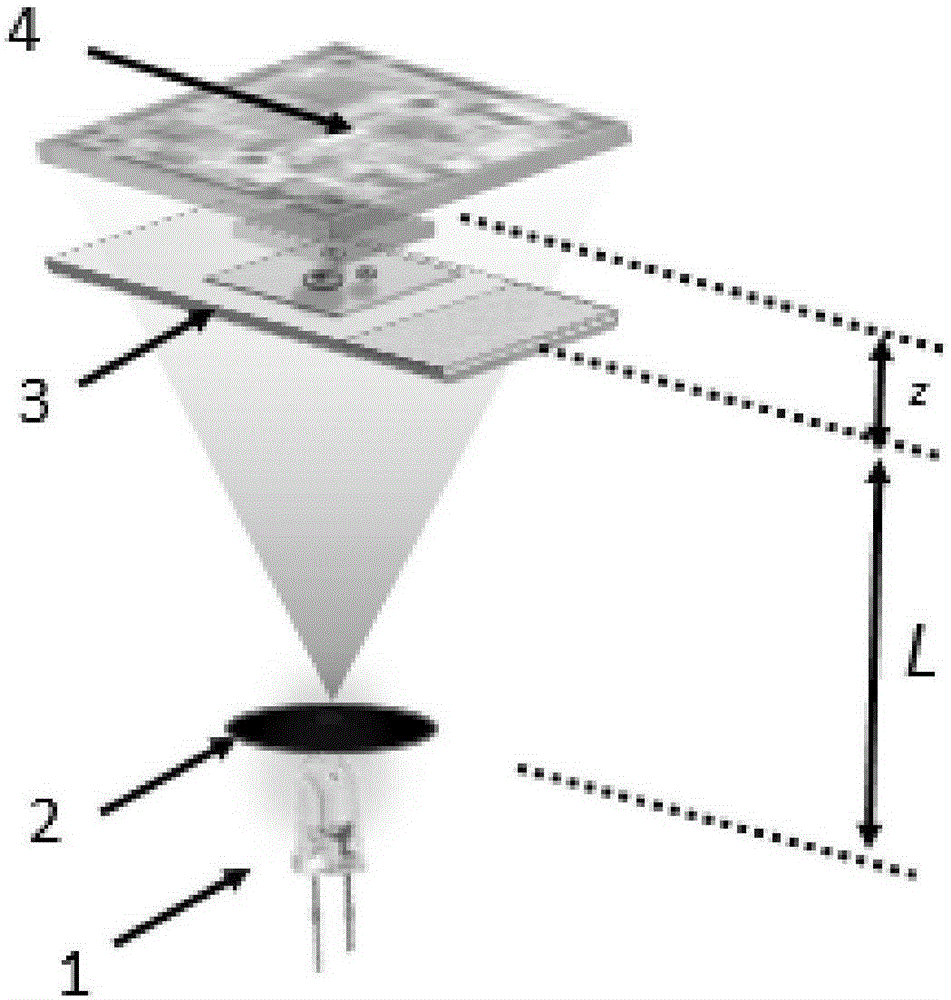
[0014] combine figure 1 , the structure of the lensless microscope based on the LED light source is as figure 1 As shown, LED light source 1, pinhole 2, sample stage 3, and camera 4 are arranged in sequence to form an imaging system. LED light source 1 is placed at the bottom of the entire imaging system, and its photosensitive surface is located on the optical axis of the entire imaging system. The pinhole 2 is close to the light-emitting surface of the LED light source 1 (within a distance of 100 microns), and the light intensity of the LED light source 1 passing through the pinhole 2 is maximized as much as possible (that is, the pinhole is facing the light-emitting surface of the LED light source 1). The distance L between the sample stage 3 and the pinhole 2 is generally between 20mm-100mm. The distance z between the camera 4 and the sample stage 3 should generally be much smaller than L, between 5 μm and 2 mm.

[0015] The LED light source 1 is used as the illumination...


PUM


Abstract

The invention discloses a lens-free microscope based on an LED light source and an image reconstruction method of the microscope. An LED light source, a pin hole, a sample table, and a camera are arranged one by one and form an imaging system. The LED light source is installed on the bottom of the whole imaging system, and a photosensitive surface of the LED light source is on the optical axis of the whole imaging system. The pin hole is close to and opposite to a light emitting surface of the LED light source. The LED light source is used as an illuminating light source of the microscope, and adopts a monochromatic LED with a central wavelength of lambda or RGB three-color LEDs. Firstly, LED is used as the illuminating light source of the microscope, and a needed light intensity image is captured; then phase information of a to-be-tested light wave field is obtained through phase recovery by means of an iterative method; and finally a computer is used to achieve inverse propagation of values and a focused image of an object under test is obtained. The microscope does not need any imaging optical element, so that the system structure is simplified, the size of the microscope is reduced, and the cost is lowered.

Description

technical field [0001] The invention belongs to optical microscopic imaging technology, in particular to a lensless microscope based on an LED light source and an image reconstruction method thereof. Background technique [0002] Optical microscopes have been the core instruments for biomedical detection and analysis since they were used for biomedical observation in the 1660s. The advent of phase contrast microscopes, differential interference phase contrast microscopes, fluorescence microscopes, and laser confocal microscopes has greatly promoted the improvement of life science research. They provide higher resolution and imaging quality for disease diagnosis, especially for major malignant diseases. Early diagnosis provides powerful imaging evidence and becomes an indispensable tool in modern clinical medicine. However, these microscope systems are still based on the "what you see is what you get" imaging method, and do not take full advantage of the powerful functions o...

Claims


Application Information

Patent Timeline
Patent Type & Authority Applications(China)
IPC IPC(8): G02B21/06
Inventor 左超陈钱孙佳嵩张佳琳顾国华张玉珍冯世杰胡岩陶天阳李加基张良孔富城张敏亮范瑶林飞
Owner NANJING UNIV OF SCI & TECH
Why Eureka
Try Eureka