
Micromechanical sensor device and corresponding production method

A sensor device and micro-mechanical technology, which can be used in semiconductor/solid-state device manufacturing, measurement devices, thermoelectric devices with thermal changes in permittivity, etc., and can solve problems such as expensive

Inactive Publication Date: 2015-12-23
ROBERT BOSCH GMBH
View PDF11 Cites 1 Cited by
  • Summary
  • Abstract
  • Description
  • Claims
  • Application Information

AI Technical Summary

Problems solved by technology

The disclosed pixel structure causes thermal crosstalk between pixel elements through its common electrode layer
Known structural elements in part require expensive, vacuum-tight packaging

Method used


Image

  • Micromechanical sensor device and corresponding production method
  • Micromechanical sensor device and corresponding production method
  • Micromechanical sensor device and corresponding production method

Examples


Embodiment Construction

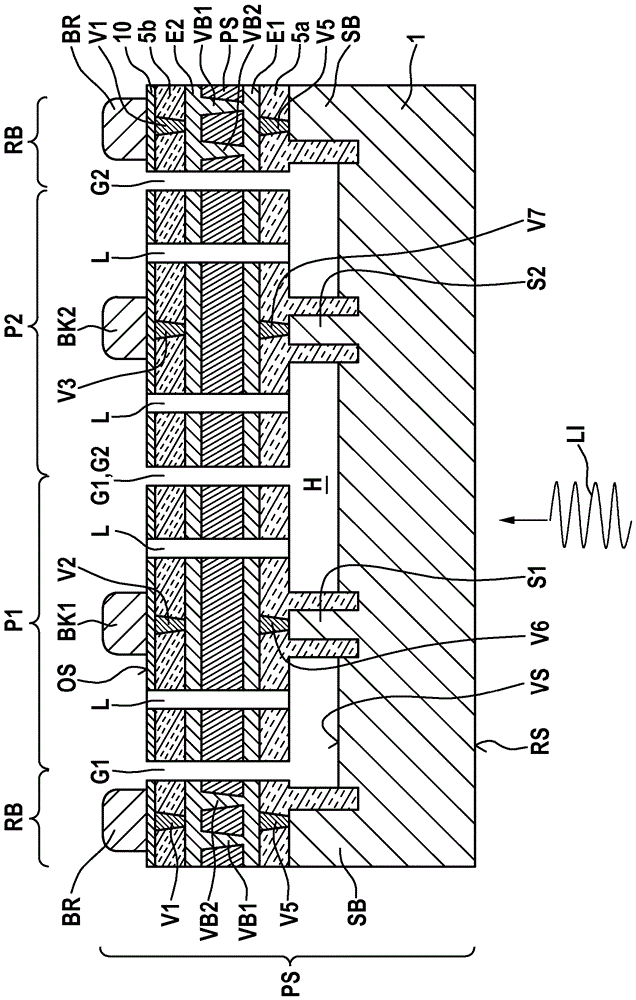
[0025] figure 1 is a schematic cross-sectional view for explaining the micromechanical sensor device according to the first embodiment of the present invention.

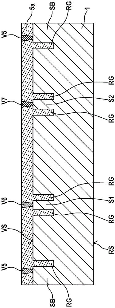
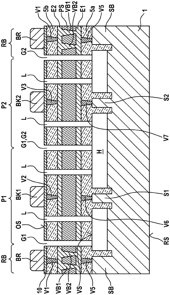
[0026] exist figure 1 In , reference numeral 1 denotes a low-resistance silicon substrate having a front side VS and a back side RS. A first post S1 and a second post S2 are formed on the front side VS of the silicon substrate 1 . A surrounding edge wall SB is formed in the edge region RB of the silicon substrate 1 .

[0027] A corresponding sensor element P1 or P2 in the form of a pyroelectric pixel element is formed on the first pillar S1 and the second pillar S2 , wherein the sensor elements P1 , P2 each have a higher thickness than the associated pillar S1 or S2. The lateral extent is large, and a cavity H is provided laterally of the pillar S1 or S2 below the sensor element P1 or P2 .

[0028] The sensor elements P1 , P2 are laterally separated from each other by respective separating grooves G1 , G2 and on ...


PUM


Abstract

The invention relates to a micromechanical sensor device and a corresponding production method. The micromechanical sensor device comprises a substrate (1) having a front (VS) and a rear (RS), a plurality of pillars (S1, S2) being formed on the front (V) of the substrate (1). On each pillar a respective sensor element (P1, P2) is formed, which has a greater lateral extent than the associated pillar (S1, S2), a cavity (H) being provided laterally to the pillars (S1, S2) beneath the sensor elements (P1, P2). The sensor elements (P1, P2) are laterally spaced apart from each other by means of respective separating troughs (G1, G2) and make electrical contact with a respective associated rear contact (V6, E1; V7, E1) via the respective associated pillar (S1, S2).

Description

technical field [0001] The invention relates to a micromechanical sensor arrangement and a corresponding production method. Background technique [0002] Although it can also be applied to any micromechanical components, the invention and the problem underlying it are explained with reference to a silicon-based pyroelectric infrared sensor. [0003] Pyroelectric infrared sensors are known from US 5,424,544 A, US 6,239,433 B1 and WO 2010 / 119131 A1. The examples described there are subject to complex, cost-intensive production processes. The disclosed pixel structure causes thermal crosstalk between pixel elements through its common electrode layer. Known structural elements in some cases require expensive, vacuum-tight packaging. Contents of the invention [0004] The invention provides a micromechanical sensor arrangement according to claim 1 and a corresponding production method according to claim 10 . [0005] Preferred refinements are the subject matter of the corre...

Claims


Application Information

Patent Timeline
Patent Type & Authority Applications(China)
IPC IPC(8): G01J5/04G01J5/02G01J5/34G01J5/08H01L21/768H01L37/02H10N15/10
CPCG01J5/045G01J5/0225G01J5/024G01J5/34G01J2005/345G01J5/0853H10N15/10H01L31/0224H01L31/09H01L31/18
Inventor G.比肖平克C.舍林
Owner ROBERT BOSCH GMBH
Learn More