Method for detecting included angle between tracking reflector and cross shaft of laser tracker

A technology of a laser tracker and a detection method, which is applied to instruments, measuring devices, and optical devices, etc., can solve the problems of processing and adjustment errors, measurement errors, deviation of the tracker beam from the ideal position, etc., and achieves good reliability and measurement accuracy. High, improve the effect of assembly and adjustment accuracy

Inactive Publication Date: 2015-12-30
扬中中科维康智能科技有限公司
View PDF4 Cites 3 Cited by
  • Summary
  • Abstract
  • Description
  • Claims
  • Application Information

AI Technical Summary

Problems solved by technology

Due to the processing and assembly errors in the mechanical structure, the tracking mirror and the horizontal axis are not in the same plane, and there is a certain angle between them. This error makes the tracker beam deviate from the ideal position, resulting in measurement errors

Method used


Image

  • Method for detecting included angle between tracking reflector and cross shaft of laser tracker
  • Method for detecting included angle between tracking reflector and cross shaft of laser tracker
  • Method for detecting included angle between tracking reflector and cross shaft of laser tracker

Examples


specific Embodiment approach

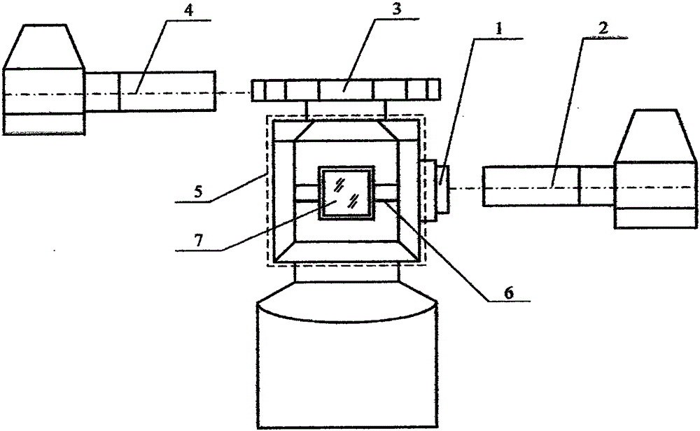
[0013] Apparatus used in the present invention such as figure 1 As shown, the device is used to detect the angle between the horizontal axis 6 on the tracking head 5 of the laser tracker and the tracking mirror 7 . Its components include a high-precision adjustable end mirror 1 , an autocollimator 2 , a polygonal prism 3 and an autocollimator 4 . Among them, 1 is fixed at one end of 6, and 2 is used to detect its position. 3 is fixed on 5, utilize 4 to detect its position. The specific implementation is as follows:

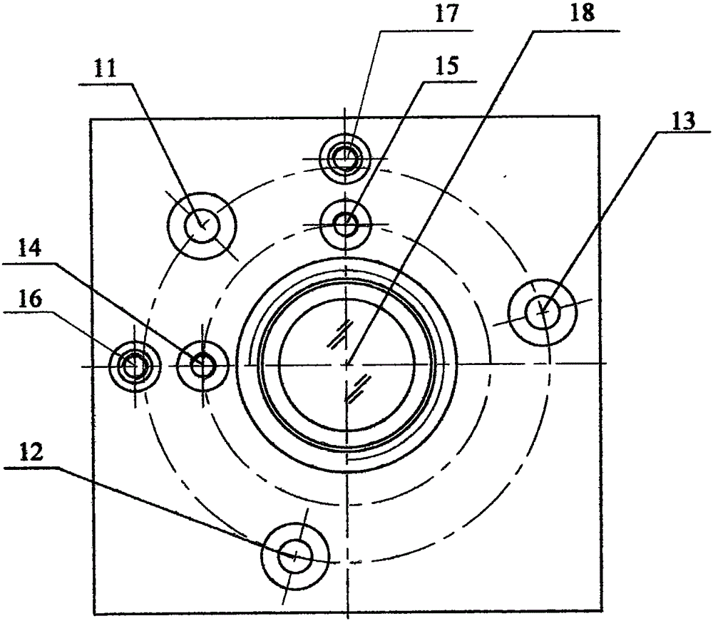
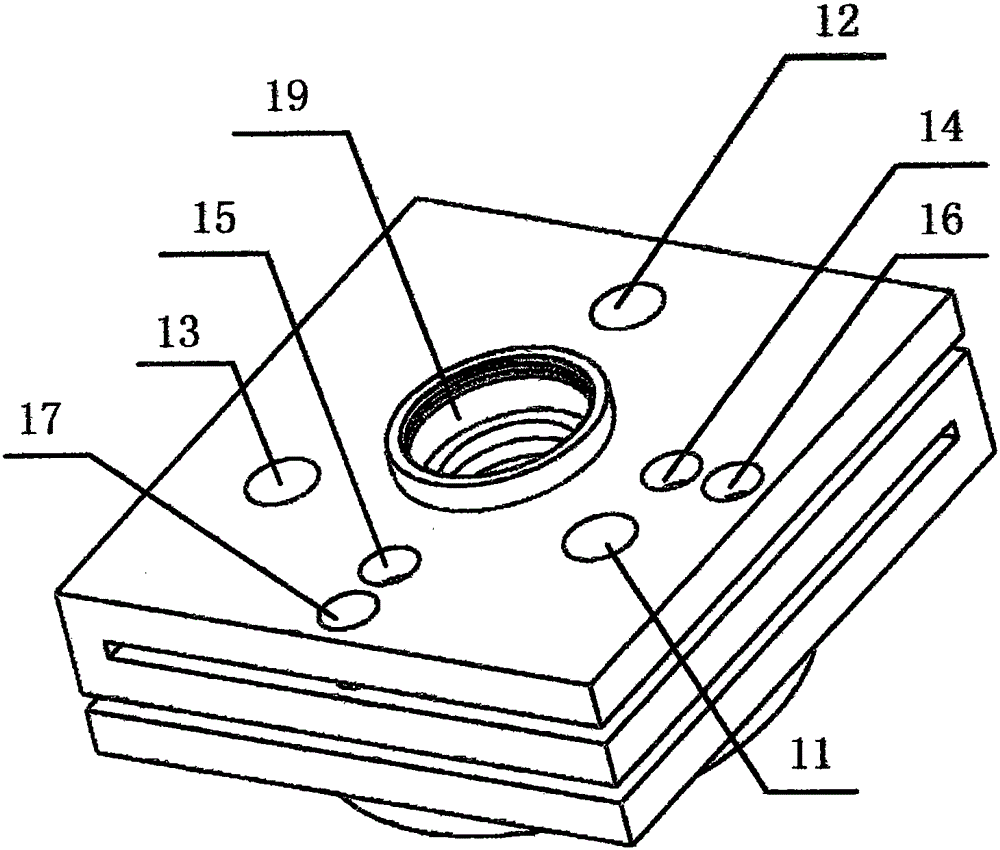
[0014] 1. As shown in Figure 2, tighten the fixing screws 11, 12, and 13 on the end face of the tracker to fix 1 on 6. The center of 1 is equipped with an end reflector 18, and what 2 detects is the specific orientation of 18 relative to 2. 1 has positive position adjustment screws 14,15 and reverse position adjustment screws 16,17. Tighten 14 and 15 respectively, then 1 tilts in the direction close to 5 in the horizontal and pitch azimuths respectively; tigh...


PUM


Abstract

The invention discloses a method for detecting the included angle between a tracking reflector and a cross shaft of a laser tracker. The method is suitable for installation adjustment and error correction of the tracking reflector of the laser tracker. The method plays an important role in designing a high-accuracy adjustable end face reflector, establishing a corresponding detection mathematic model and providing high-accuracy standard angles through autocollimators and a polyhedron.

Description

technical field [0001] The invention relates to a method for detecting the included angle between a laser tracker tracking reflector and a horizontal axis, which is suitable for installation adjustment and error correction of the laser tracker track reflector. Background technique [0002] At present, there is still a gap in the manufacture of laser trackers in China, lack of methods for detecting and adjusting geometric structure errors of trackers, and there are no related technical patents and literature reports. [0003] The tracking mirror of the laser tracker is used to point the laser beam to the target to be measured. Ideally the abscissa should be coplanar with the mirror surface of the tracking mirror. Due to the processing and assembly errors in the mechanical structure, the tracking mirror and the horizontal axis are not coplanar, and there is a certain angle between them. This error makes the tracker beam deviate from the ideal position, resulting in measuremen...

Claims


Application Information

Patent Timeline
Patent Type & Authority Applications(China)
IPC IPC(8): G01B11/26
Inventor 陈万荣陈修祥周维虎孙华平
Owner 扬中中科维康智能科技有限公司
Why Eureka
Try Eureka