Tile flatness detecting method and device

A technology for flatness detection and tiles, which is applied in the field of ceramic processing, and can solve problems such as deformation data and calibration difficulties of ceramic tiles that are easy to miss

Active Publication Date: 2015-12-30
GUANGDONG SINID TECH
View PDF6 Cites 10 Cited by
  • Summary
  • Abstract
  • Description
  • Claims
  • Application Information

AI Technical Summary

Problems solved by technology

This method is difficult to calibrate, and it is easy to miss the deformation data of some tiles

Method used


Image

  • Tile flatness detecting method and device
  • Tile flatness detecting method and device

Examples


Embodiment 1

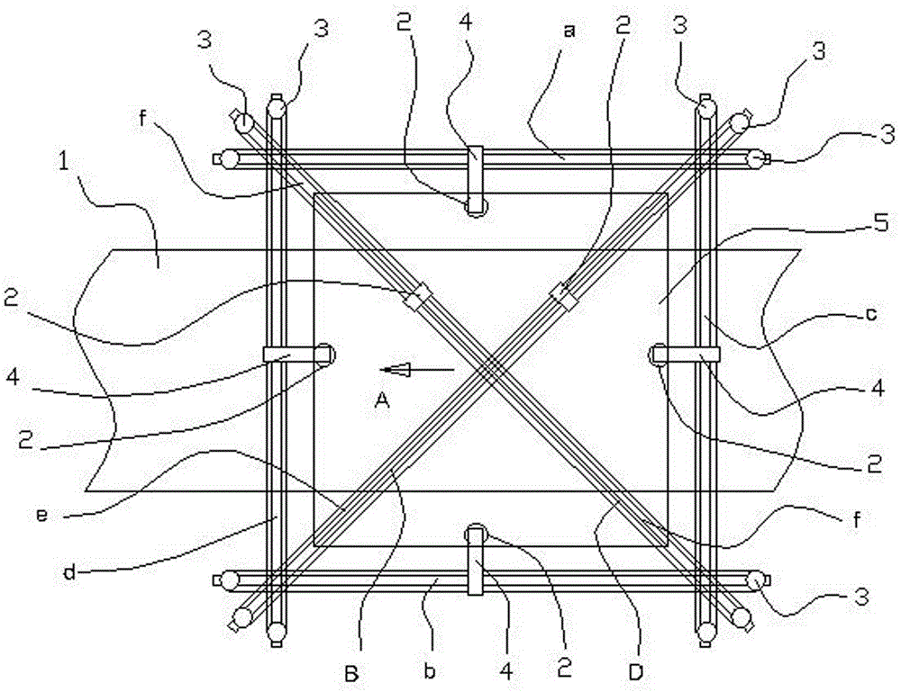
[0013] Embodiment one: if figure 1 As shown, the tile flatness detection device of the present invention is realized in this way, including an upper linear guide rail a arranged horizontally on both sides of the tile conveying device 1, a lower linear guide rail b, and two vertical rails perpendicular to the tile conveying direction A. Linear guide rails c, d, oblique linear guide rails e, f corresponding to tile diagonal directions B, D, and laser displacement sensors 2 slidingly arranged on each linear guide rail. The detection direction of laser displacement sensor 2 is downward, and each linear guide rail The laser displacement sensor 2 on the top is driven by the electric power mechanism 3 to move.

[0014] Here, a movable frame 4 driven by the electric power mechanism 3 is slidably arranged on the linear guide rail, and the movable frame 4 floats out to the top of the ceramic tile 5, and the laser displacement sensor 2 is arranged on the movable frame 4 floating out, so ...

Embodiment 2

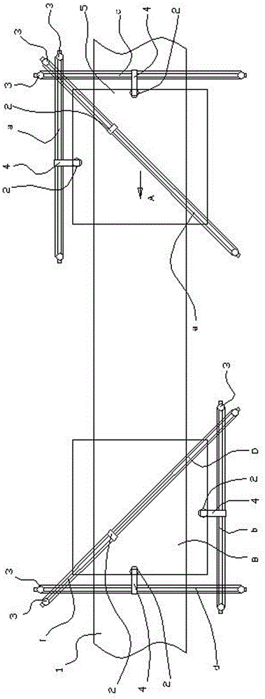
[0015] Embodiment two: if figure 2 As shown, this embodiment is based on the first embodiment, the upper linear guide rail a with the laser displacement sensor 2 arranged horizontally on one side of the tile conveying device 1, and one of the linear guides a perpendicular to the tile conveying direction A The vertical linear guide rail c of the laser displacement sensor 2 and the oblique linear guide rail e with the laser displacement sensor 2 corresponding to one pair of corner directions B of the tiles are the first group, which are arranged at the level of the other side of the tile conveying device 1 The upper linear guide rail b with laser displacement sensor 2, the other vertical linear guide rail d with laser displacement sensor 2 perpendicular to the tile conveying direction A, and the vertical linear guide rail d with laser displacement sensor 2 corresponding to the other diagonal direction D of the tiles. The oblique linear guide rail f of sense 2 is the second grou...


PUM


Abstract

The invention discloses a tile flatness detecting method and device. The device is characterized by comprising an upper linear guide rail and a lower linear guide rail which are horizontally arranged on the two sides of a tile conveying device, a vertical straight line guide rail perpendicular to the tile conveying direction, an inclined straight line guide rail corresponding to the tile diagonal direction, and laser displacement sensors which are arranged on the straight line guide rails in a sliding mode respectively, the detection direction of the laser displacement sensors faces downwards, and the laser displacement sensors on the straight line guide rails are driven by an electric power mechanism to move. Compared with the prior art, the tile flatness detecting method and device have the advantages that calibration is not needed and tile deformation detection omission is not prone to occurrence.

Description

Technical field: [0001] The invention relates to a ceramic processing technology. Background technique: [0002] The traditional ceramic tile plane detection equipment uses 5~7 laser displacement sensors to detect the flatness. The sensors are fixed on the beam at a certain interval. After the tiles pass through, the flatness of the tiles can be obtained by calculation. This method is difficult to calibrate, and it is easy to miss the deformation data of some tiles. Invention content: [0003] The object of the present invention is to provide a tile flatness inspection method and device that do not require calibration and are not easy to miss the deformation of tiles. [0004] The tile flatness detection method of the present invention is realized in this way, in the tile conveying process, respectively use several laser displacement sensors moving along the linear guide rails to continuously detect the distance between the tile surface and the laser displacement sensors ...

Claims


Application Information

Patent Timeline
Patent Type & Authority Applications(China)
IPC IPC(8): G01B11/30
Inventor 杨扬
Owner GUANGDONG SINID TECH
Why Eureka
Try Eureka