Ammonia concentration detection method and photoetching process figure critical dimension (CD) control method

An ammonia concentration and photolithography technology, which is applied in photoplate-making process exposure devices, patterned surface photoplate-making processes, and microlithography exposure equipment, etc., can solve wafer defects, CD changes, and ammonia concentration accuracy. Low problems, to avoid wafer defects, accurate ammonia concentration, and accurate detection results

Active Publication Date: 2015-12-30
SEMICON MFG INT (SHANGHAI) CORP +1
View PDF5 Cites 5 Cited by
  • Summary
  • Abstract
  • Description
  • Claims
  • Application Information

AI Technical Summary

Problems solved by technology

[0008] In view of the shortcomings of the prior art described above, the purpose of the present invention is to provide a method for detecting the concentration of ammonia gas and a method for controlling the pattern CD in the photolithography process, which is used to solve the problems caused by the internal problems of the photolithography machine in the prior art. The detection of the ammonia concentration in the lithography machine will affect the production operation of the lithography machine, so the problem that it cannot be detected frequently, and solve the problem that the detection method of the prior art is used due to the uneven distribution of the ammonia gas concentration inside the lithography machine. , the problem of low accuracy of the ammonia gas concentration inside the lithography machine is obtained. In addition, it also solves the problem that the existing technology cannot control the CD of the pattern in the lithography process according to the influence of the ammonia gas concentration on the CD, resulting in the lithography When the exposed photoresist in the process is delayed in baking after exposure, it is affected by the ammonia gas inside the lithography machine, which leads to CD changes and wafer defects.

Method used


Image

  • Ammonia concentration detection method and photoetching process figure critical dimension (CD) control method
  • Ammonia concentration detection method and photoetching process figure critical dimension (CD) control method
  • Ammonia concentration detection method and photoetching process figure critical dimension (CD) control method

Examples


Embodiment Construction

[0059] Embodiments of the present invention are described below through specific examples, and those skilled in the art can easily understand other advantages and effects of the present invention from the content disclosed in this specification. The present invention can also be implemented or applied through other different specific implementation modes, and various modifications or changes can be made to the details in this specification based on different viewpoints and applications without departing from the spirit of the present invention.

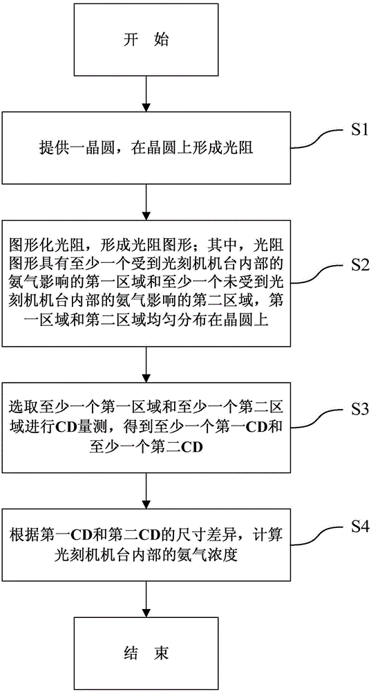
[0060] see image 3 , the embodiment of the present invention relates to a method for detecting the concentration of ammonia gas, which is used to detect the concentration of ammonia gas inside the lithography machine. It should be noted that the diagrams provided in this embodiment are only schematically illustrating the basic idea of ​​the present invention, and only the components related to the present invention are shown in the d...


PUM


Abstract

The invention provides an ammonia concentration detection method. The ammonia concentration detection method is used for detecting a concentration of ammonia in a photoetching machine. The method comprises S1, providing a wafer and forming light resistance on the wafer, S2, carrying out light resistance imaging to obtain a light resistance figure, wherein the light resistance figure comprises at least one first area influenced by ammonia in the photoetching machine and at least one second area uninfluenced by ammonia in the photoetching machine, wherein the first area and the second area are uniformly distributed on the wafer, S3, selecting the at least one first area and the at least one second area and carrying out critical dimension (CD) measurement to obtain at least one first CD and at least one second CD, and S4, according to the size difference of the first SD and the second CD, calculating an ammonia concentration in the photoetching machine. The method utilizes a CD measurement method to detect an ammonia concentration in the photoetching machine, produces minimum influence on photoetching machine production and realizes frequent detection.

Description

technical field [0001] The invention relates to the technical field of semiconductors, in particular to a method for detecting ammonia gas concentration and a method for controlling pattern CD in a photolithography process. Background technique [0002] ASML (ASMLHoldingN.V.) is a semiconductor equipment manufacturer in the Netherlands. The main products of ASML are the stepper lithography machine (Stepper), which is the core equipment used to produce large-scale integrated circuits, and the scanning lithography machine (Scanner), which is used to manufacture integrated circuits with 37nm line width. For ASML's Scanner, in the lithography process (LithoProcess), it is necessary to strictly control the time of the wafer from the exposure unit to the hot plate (HotPlate) of the postexposure bake (PostExposureBake, PEB) unit after exposure, which is generally required. Controlled within 400 seconds, the interval between the exposure unit and the post-exposure bake unit is call...

Claims


Application Information

Patent Timeline
Patent Type & Authority Applications(China)
IPC IPC(8): G03F7/20G03F1/44G01N33/00
Inventor 王清蕴卢子轩
Owner SEMICON MFG INT (SHANGHAI) CORP
Why Eureka
Try Eureka