Method for detecting ammonia gas concentration and method for controlling pattern cd in photolithography process

A technology of ammonia gas concentration and lithography process, which is applied in the direction of photolithography process exposure device, pattern surface photolithography process, micro-lithography exposure equipment, etc., can solve wafer defects, CD changes, ammonia concentration accuracy Low-level problems, to avoid the occurrence of wafer defects, accurate ammonia concentration, and reduce interference factors

Active Publication Date: 2017-07-28
SEMICON MFG INT (SHANGHAI) CORP +1
View PDF5 Cites 0 Cited by
  • Summary
  • Abstract
  • Description
  • Claims
  • Application Information

AI Technical Summary

Problems solved by technology

[0008] In view of the shortcomings of the prior art described above, the purpose of the present invention is to provide a method for detecting the concentration of ammonia gas and a method for controlling the pattern CD in the photolithography process, which is used to solve the problems caused by the internal problems of the photolithography machine in the prior art. The detection of the ammonia concentration in the lithography machine will affect the production operation of the lithography machine, so the problem that it cannot be detected frequently, and solve the problem that the detection method of the prior art is used due to the uneven distribution of the ammonia gas concentration inside the lithography machine. , the problem of low accuracy of the ammonia gas concentration inside the lithography machine is obtained. In addition, it also solves the problem that the existing technology cannot control the CD of the pattern in the lithography process according to the influence of the ammonia gas concentration on the CD, resulting in the lithography When the exposed photoresist in the process is delayed in baking after exposure, it is affected by the ammonia gas inside the lithography machine, which leads to CD changes and wafer defects.

Method used


Image

  • Method for detecting ammonia gas concentration and method for controlling pattern cd in photolithography process
  • Method for detecting ammonia gas concentration and method for controlling pattern cd in photolithography process
  • Method for detecting ammonia gas concentration and method for controlling pattern cd in photolithography process

Examples


Embodiment Construction

[0059] The following describes the implementation of the present invention through specific specific examples. Those skilled in the art can easily understand other advantages and effects of the present invention from the content disclosed in this specification. The present invention can also be implemented or applied through other different specific embodiments, and various details in this specification can also be modified or changed based on different viewpoints and applications without departing from the spirit of the present invention.

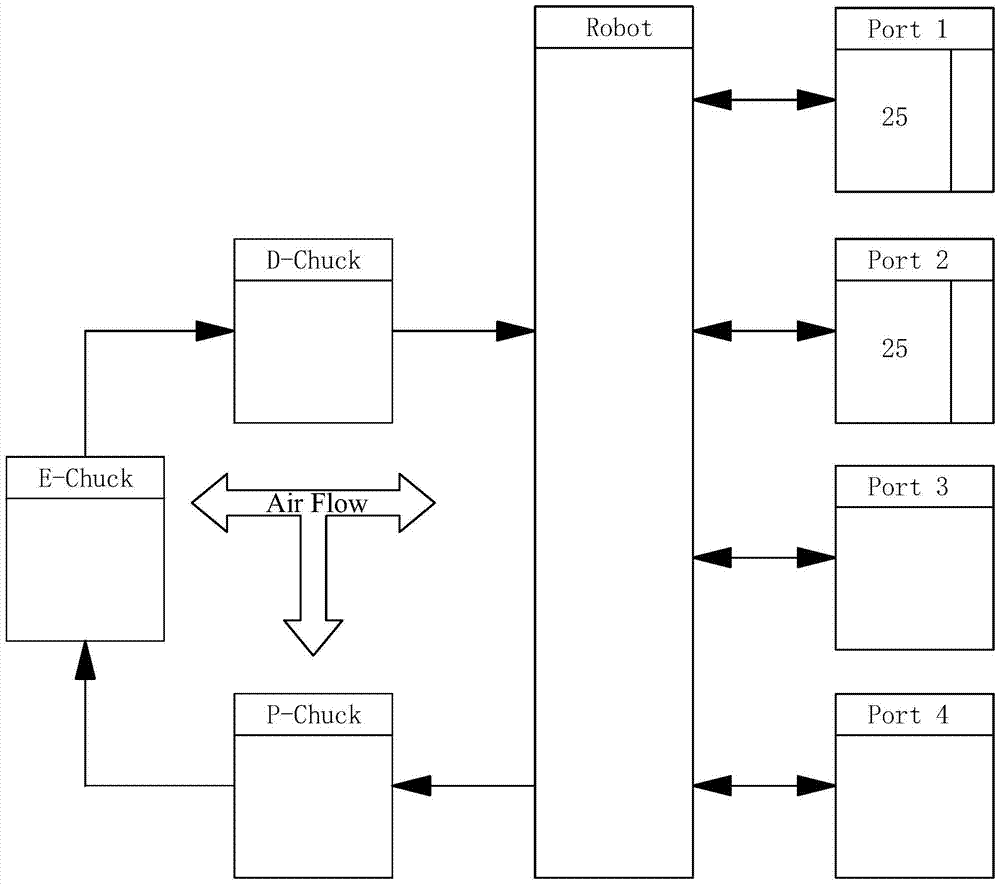
[0060] See image 3 The embodiment of the present invention relates to an ammonia gas concentration detection method for detecting the ammonia gas concentration inside the lithography machine. It should be noted that the illustrations provided in this embodiment only illustrate the basic idea of ​​the present invention in a schematic way, and the figures only show the components related to the present invention instead of the number, shape, an...


PUM


Abstract

The present invention provides a method for detecting the concentration of ammonia gas, which is used to detect the concentration of ammonia gas inside the photolithography machine, at least including: step S1, providing a wafer, and forming a photoresist on the wafer; step S2, pattern The photoresist is formed to form a photoresist pattern; wherein, the photoresist pattern has at least one first area affected by the ammonia gas inside the photolithography machine platform and at least one second area not affected by the ammonia gas inside the photolithography machine platform area, the first area and the second area are evenly distributed on the wafer; step S3, select at least one first area and at least one second area for CD measurement, and obtain at least one first CD and at least one second CD; step S4, according to the size difference between the first CD and the second CD, calculate the ammonia gas concentration inside the photolithography machine. The invention adopts the method of measuring CD to detect the ammonia gas concentration inside the lithography machine, which minimizes the impact on the production operation of the lithography machine and can be frequently detected.

Description

Technical field [0001] The invention relates to the field of semiconductor technology, in particular to a method for detecting the concentration of ammonia gas and a method for controlling the pattern CD in the photolithography process. Background technique [0002] ASML (ASML Holding N.V.) is a Dutch semiconductor equipment manufacturer. ASML's main products are the stepper (Stepper), the core equipment used to produce large-scale integrated circuits, and the Scanner (Scanner), used to manufacture 37nm line-width integrated circuits. For ASML Scanner, in the Litho Process, it is necessary to strictly control the time of the wafer from the exposure unit to the hot plate (Hot Plate) of the Post Exposure Bake (PEB) unit after exposure, generally The time is required to be controlled within 400 seconds. The time between the exposure unit and the post-exposure bake unit is called PEB Delay. If the baking delay time after exposure is too long, it will have a certain impact on the ph...

Claims


Application Information

Patent Timeline
Patent Type & Authority Patents(China)
IPC IPC(8): G03F7/20G03F1/44G01N33/00
Inventor 王清蕴卢子轩
Owner SEMICON MFG INT (SHANGHAI) CORP
Why Eureka
Try Eureka