Current control circuit

A technology of current control circuit and circuit, which is applied in control/regulation system, regulation of electrical variables, instruments, etc., can solve the problems of narrow application range, large output current fluctuation, poor current stability, etc., and achieve wide current output range, current The effect of high output accuracy and stable output current

Inactive Publication Date: 2015-12-30
ZHENGZHOU JINYUAN ELECTROMECHANICAL EQUIP ENG CO LTD
View PDF0 Cites 0 Cited by
  • Summary
  • Abstract
  • Description
  • Claims
  • Application Information

AI Technical Summary

Problems solved by technology

The current control circuit in the prior art generally has complex structure, too large circuit, narrow application range, poor current stability, and large fluctuation of output current, which cannot meet some high requirements for current. Therefore, the current control circuit is changed for optimization. Design and improvement to meet actual needs has become a problem that must be solved in front of technical personnel in the field

Method used


Image

  • Current control circuit

Examples


Embodiment Construction

[0006] The present invention will be described in detail below in conjunction with the drawings.

[0007] In order to make the objectives, technical solutions and advantages of the present invention clearer, the following further describes the present invention in detail with reference to the accompanying drawings and embodiments. It should be understood that the specific embodiments described herein are only used to explain the present invention, but not to limit the present invention.

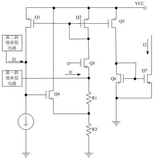
[0008] Such as figure 1 Shown is a schematic diagram of a current control circuit of the present invention. A current control circuit includes a first slope compensation circuit and a second slope compensation circuit, and also includes PMOS tubes Q1 to Q3, NMOS tubes Q4 to Q7, resistors R1 and R2, and a constant current source; the drain of PMOS tube Q1 is connected to NMOS The gate of the tube Q4 and one end of the constant current source, the source is connected to the drain of the NMOS tube ...


PUM


Abstract

The invention discloses a current control circuit. The current control circuit comprises a first slope compensation circuit and a second slope compensation circuit, and further comprises PMOS transistors (Q1-Q3), NMOS transistors (Q4-Q7), resistors (R1 and R2) and a constant current source. The drain electrode of the Q1 is connected with the grid electrode of the Q4 and one end of the constant current source. The source electrode of the Q1 is connected with the drain electrode of the Q4, the source electrodes of the Q2 and the Q3 and a voltage source VCC. The grid electrode of the Q1 is connected with the grid electrodes of the Q2 and the Q3, the drain electrode of the Q2 and the drain electrode of the Q5. The R1 and the R2 are connected in series, then, one end is grounded, and the other end is connected with the source electrode of the Q5. The source electrode of the Q4 is connected with the common end of the R1 and the R2. The drain electrode of the Q6 is connected with the drain electrode of the Q3, the grid electrode of the Q6 and the grid electrode of the Q7. The source electrode of the Q6 is grounded. The other end of the constant current source is grounded. The other end of the Q7 is grounded. The slope compensation currents (I1 and I3) are connected with the source electrode of the Q5 and the drain electrode of the Q1 respectively. The current control circuit has the advantages that the structure is simple, the precision of current output is high, the range of the current output is wide, and the current is stable.

Description

Technical field [0001] The invention relates to a current control circuit. Background technique [0002] In some control fields, the current requirements of the circuit have small fluctuations, good stability, and large controllable range. Current control circuits in the prior art generally have complex structures, too large circuits, narrow application ranges, poor current stability, and large output current fluctuations, which cannot meet some requirements for high currents. Therefore, the current control circuit is changed to optimize Design and improvement to meet actual needs have become a problem that must be solved before the field technicians. Summary of the invention [0003] The purpose of the present invention is to provide a current control circuit for the above-mentioned problems, which includes a first slope compensation circuit and a second slope compensation circuit, and also includes PMOS transistors Q1 to Q3, NMOS transistors Q4 to Q7, resistor R1 and R2 and co...

Claims


Application Information

Patent Timeline
Patent Type & Authority Applications(China)
IPC IPC(8): G05F1/46
Inventor 赵迪
Owner ZHENGZHOU JINYUAN ELECTROMECHANICAL EQUIP ENG CO LTD
Why Eureka
Try Eureka