Radial fan-shaped magnetic focusing system for radial beam traveling-wave tube

A magnetic focusing and fan-shaped technology, which is applied in the field of radial fan-shaped magnetic focusing system and magnetic focusing system, can solve the problems affecting the focusing effect, etc., and achieve the effect of improving the focusing effect and the effect

Active Publication Date: 2015-12-30
UNIV OF ELECTRONIC SCI & TECH OF CHINA
View PDF8 Cites 7 Cited by
  • Summary
  • Abstract
  • Description
  • Claims
  • Application Information

AI Technical Summary

Problems solved by technology

However, when the conventional magnetic focusing system is used to focus the radial fan-shaped ribbon-shaped electron beam, θ is relatively large, and the change of the ele

Method used


Image

  • Radial fan-shaped magnetic focusing system for radial beam traveling-wave tube
  • Radial fan-shaped magnetic focusing system for radial beam traveling-wave tube
  • Radial fan-shaped magnetic focusing system for radial beam traveling-wave tube

Examples


Embodiment 1

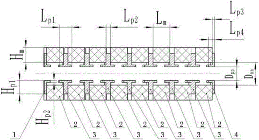
[0037] A radial sector magnetic focusing system for a radial beam traveling wave tube, the magnetic focusing system includes a permanent magnet 2 and a pole shoe 3, the cross section of the permanent magnet 2 is rectangular, and the cross section of the pole shoe 3 is T type, the two ends of the magnetic focusing system are permanent magnets 2, that is, the arrangement of permanent magnets 2 and pole shoes 3 is "permanent magnet 2—pole shoe 3—permanent magnet 2—pole shoe 3—...—pole shoe 3—permanent Magnet 2—pole shoe 3—permanent magnet 2”, pole shoe 3 and permanent magnet 2 are arranged at intervals and mirrored by 180° rotation along the central axis of the radial electron beam.

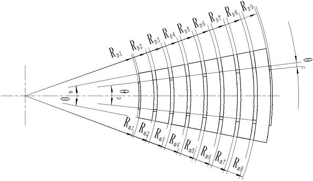
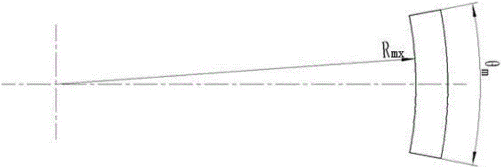
[0038] The shape of the permanent magnet 2 is fan-shaped, and the small radius Rmx=Rpb2+(x-1)(Lm+Lp2) of the xth group of permanent magnets 2, x=(1, 2, 3...f, f≤20) , the radial length Lm=(0.9~4)mm of the xth group of permanent magnets 2, the axial height Hm=(0.7~6)mm of the xth group of permanent m...

Embodiment 2

[0047] On the basis of Embodiment 1, in this embodiment, the radial length Lm=1.9mm of each group of permanent magnets 2, the axial height Hm=2mm of each group of permanent magnets 2, the angular angle θm of each group of permanent magnets 2 = 200°. The radial length Lp1 of the side wall of the yth group of pole pieces 3 = 1.4 mm, the radial thickness Lp2 of the spacer plate of the yth group of pole pieces 3 = 0.5 mm, and the angular angle θp of the yth group of pole pieces 3 = 180° , where, Rpb2 = 16.65mm. The stagger angle between the pole piece 3 of the yth group and the pole piece 3 of the y+1 group is (-1) (y+1)× θc, y=(1, 2, 3...78, 79), θc=10°. The pole shoes 3 of the upper row and the pole shoes 3 of the lower row form a pole shoe 3 gap Dpp=1.56mm at an interval of Dpp; the permanent magnets 2 of the upper row and the permanent magnets 2 of the lower row form a magnet gap with an interval of Dmm, Dmm= 2.56mm. The small radius Rpb1 of the spacer plate of the small h...


PUM

PropertyMeasurementUnit
Radial lengthaaaaaaaaaa
Axial heightaaaaaaaaaa
Radial thicknessaaaaaaaaaa

Abstract

The invention discloses a radial fan-shaped magnetic focusing system for a radial beam traveling-wave tube, and belongs to magnetic focusing systems in the technical field of vacuum electron devices. A magnetic field distributed in the radial direction is generated by the focusing system, and the direction of the magnetic field is divergent in the radial direction, so that a radial component of the magnetic field and a moving trajectory of a radial electron beam are consistent, and the focusing effect of the focusing system on the radial fan-shaped electron beam is improved. According to the technical scheme, the radial fan-shaped magnetic focusing system for the radial beam traveling-wave tube comprises a permanent magnet with the cross section shaped like a rectangle and a pole shoe with the cross section shaped like a T, the permanent magnet is shaped like a fan, and the pole shoe is shaped like a fan. Due to the fact that the permanent magnet and the pole shoe are both designed to be of a fan-shaped structure, the direction of the radial magnet field generated by the radial fan-shaped magnetic focusing system is in a radial mode, the direction of the radial magnetic field is matched with the moving trajectory of the electron beam which runs in a radial mode, and the focusing effect of the focusing system on the electron beam is significantly improved.

Description

technical field [0001] The invention belongs to the technical field of vacuum electronic devices, and relates to a magnetic focusing system, in particular to a radial sector magnetic focusing system for a radial beam traveling wave tube. Background technique [0002] A typical traveling wave tube consists of five parts: electron gun, focusing system, slow wave line (slow wave structure), input and output devices and collector. As the core component of the traveling wave tube, the function of the slow wave line is to transmit the high-frequency electromagnetic traveling wave and reduce the phase velocity of the electromagnetic wave, thereby realizing the interaction between the electromagnetic wave and the electron beam, and making the electron beam hand over DC energy to amplify the high-frequency field. Its performance directly determines the working bandwidth, output power and efficiency of the traveling wave tube. [0003] On October 24, 2012, the University of Electroni...

Claims


Application Information

Patent Timeline
IPC IPC(8): H01J23/087
Inventor 李新义石先宝王战亮宫玉彬魏彦玉段兆云黄民智
Owner UNIV OF ELECTRONIC SCI & TECH OF CHINA
Why Eureka
Try Eureka