Eureka AIR delivers breakthrough ideas for toughest innovation challenges, trusted by R&D personnel around the world.

Drive and system having at least one driven cylinder or extruder screw

A driver and electric drive technology, which is applied in paper machines, calenders, textiles and papermaking, etc., can solve the problems of shortened life of the driver, high maintenance cost, and complicated sealing, so as to reduce bearing stress, compensate for component tolerances, and prevent bearings from tension effect

Inactive Publication Date: 2015-12-30
STARLINGER & CO GMBH
View PDF7 Cites 0 Cited by
  • Summary
  • Abstract
  • Description
  • Claims
  • Application Information

AI Technical Summary

Problems solved by technology

Rotating two-way seal feed-throughs are also more complex in terms of sealing against the environment in principle and in both coolant passages are more expensive to maintain in comparison
Another drawback is that the necessary motor cooling can be achieved only through the external drive housing, so higher winding temperatures will be maintained in the motor, which will in turn be reflected in the shortened lifetime of the drive

Method used


Image

  • Drive and system having at least one driven cylinder or extruder screw
  • Drive and system having at least one driven cylinder or extruder screw

Examples


Embodiment Construction

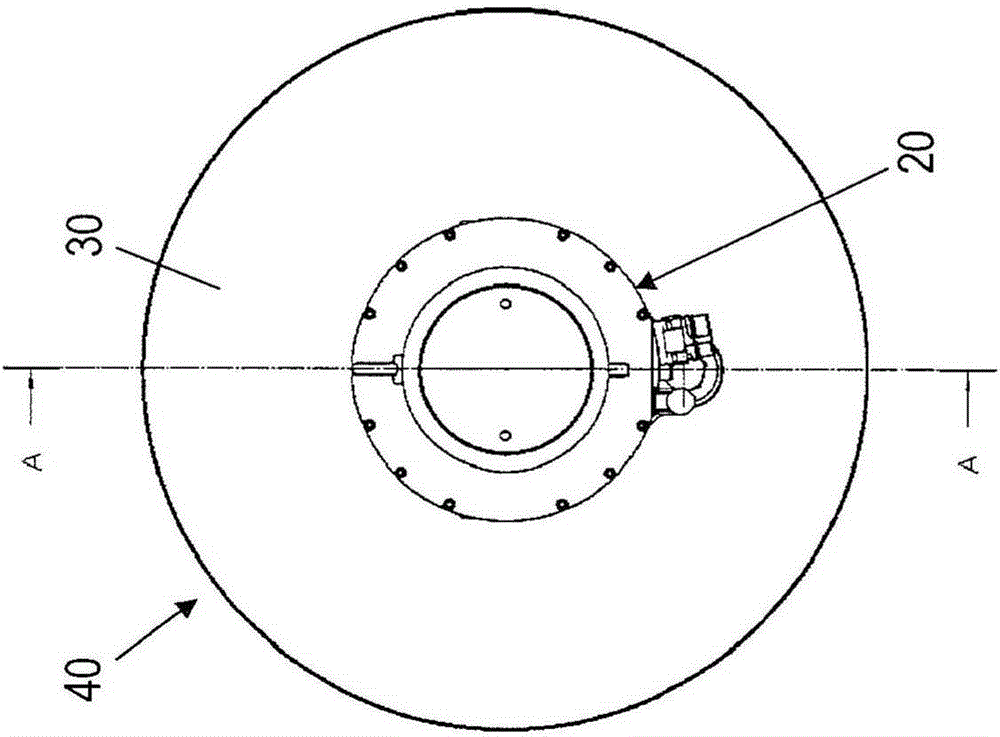
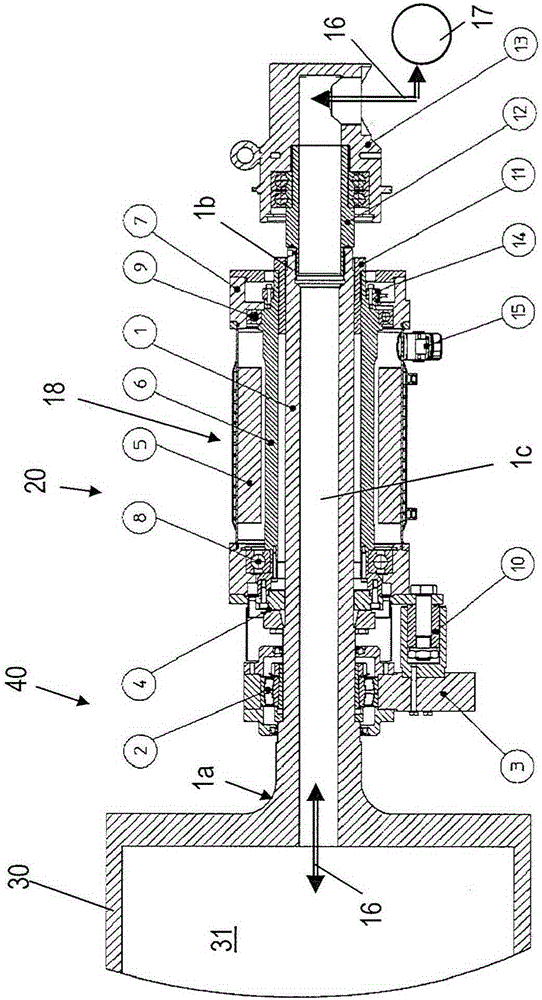
[0028] figure 1 A system 40 with rollers 30 and drives 20 is shown. The roll 30 is configured as a cooling roll, casting roll, smoothing roll, calender roll or stretching roll. As an alternative to the rollers, an extruder with an extruder screw which is driven by the drive 20 can also be provided.

[0029]The drive comprises a drive shaft 1 and an electric drive motor 18 having a rotor 6 and a stator 5 coaxially surrounding the rotor, the stator 5 having a winding. The rotor 6 is non-rotatably connected to the drive shaft 1 via a clamping device 4 arranged on the housing surface of the drive shaft 1 . The clamping device 4 is configured as a friction-fitting conical tension element, therefore, a play-free assembly. The drive shaft 1 is integral with the connection end 1 a and is thus integrally formed in the roller 30 non-rotatably. The stator 5 is held non-rotatably by being non-rotatably connected to the motor housing 7 and by the motor housing being non-rotatably preci...


PUM


Abstract

A drive (20) for a cylinder (30) or worm screw has a drive shaft (1) and an electric drive motor (18) having a rotor (6) and a stator (5). The rotor (6) is fixed to the drive shaft (1) for conjoint rotation. At a connection end (1a), the drive shaft (1) is connected to the cylinder or worm screw for conjoint rotation. The stator (5) is non-rotatably retained by a stationary component of the drive. The rotor (6) is mounted so as to be axially rotatable on a motor housing (7) with a motor bearing (8) facing the connection end (1a) of the drive shaft and with a motor bearing (9) facing away from the connection end (1a) of the drive shaft. The drive shaft (1) is guided coaxially with the rotor (6) through the drive motor (18) and beyond the drive motor (18), where the drive shaft has a free end (1b). The drive shaft is constructed as a hollow shaft having an axial temperature control medium channel (1c), which is coupled at the free end (1b) of the drive shaft to a temperature control medium connection (12, 13).

Description

Background technique [0001] Smoothing drums or smoothing rolls and calender rolls respectively have been known for producing flat foil webs and discs, in particular made of plastics material, for further processing in thermoforming equipment. For the production of flat foil webs, an arrangement of several smooth rolls is frequently employed, wherein these smooth rolls are usually configured with coolant channels for rapid cooling of the product or melt respectively. [0002] It is further known to operate such rolls at relatively low speeds in the range of 1 to 500 rpm (revolutions per minute). Since conventional electric drive motors typically have higher RPM or do not operate optimally in the low RPM range mentioned above, it is necessary to reduce the torque in conventional gear sets, chain drives or belt drives or combinations thereof. Rotating speed. It is known that mechanical gear sets and chain drives typically have tolerances for gearing reasons which are reflected ...

Claims


Application Information

Patent Timeline
Patent Type & Authority Applications(China)
IPC IPC(8): D21G1/00B29C33/04B29C47/08B29C47/60B29C43/46B29C43/24B29C47/84D21F7/02B29C48/395B29C48/82B29C48/92
CPCB29C43/24B29C43/46B29C43/52D21F7/02D21G1/0006B29C48/08B29C48/82B29C48/252B29C48/03B29C48/84B29C48/355B29C48/914B29C48/2522B29C33/044B29C2043/3277
Inventor 哈拉尔德·霍勒
Owner STARLINGER & CO GMBH
Why Eureka
Eureka Blog
Learn More