Galvano scanner and laser machining device

A technology of electronic scanner and light deflection, which is applied in laser welding equipment, metal processing equipment, instruments, etc., can solve problems such as errors, and achieve the effects of reducing surface tilt resonance and high position accuracy

Active Publication Date: 2015-12-30
MITSUBISHI ELECTRIC CORP
View PDF8 Cites 4 Cited by
  • Summary
  • Abstract
  • Description
  • Claims
  • Application Information

AI Technical Summary

Problems solved by technology

Due to the occurrence of surface tilt resonance, the traveling direction of the laser beam from the

Method used


Image

  • Galvano scanner and laser machining device
  • Galvano scanner and laser machining device
  • Galvano scanner and laser machining device

Examples


Example Embodiment

[0025] Embodiment 1.

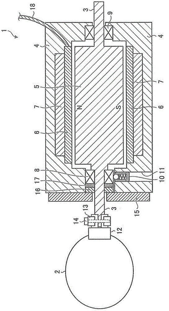
[0026] figure 1 It is a figure which shows the cross-sectional structure of the galvano scanner concerning Embodiment 1 of this invention. The galvano scanner 1 scans the object to be processed with laser light from a laser light source. The galvano scanner 1 is composed of a rotating body and a fixed body.

[0027] The rotating body has a scanning mirror 2 , a rotating shaft 3 , and a magnet 5 . The rotating body is rotatable around the rotating shaft 3 . The scanning mirror 2 is a mirror that deflects incident light. The scanning mirror 2 is connected to one end on the front side of the rotating shaft 3 . The mirror mount 12 connects the scanning mirror 2 and the rotation shaft 3 . The mount pressing tool 13 fixes the mirror mount 12 to the rotating shaft 3 in a state in which the fastener 14 is inserted. The magnet 5 is located between the front bearing 8 and the rear bearing 9 .

[0028] The fixed body has the frame case 4 , the winding 6 , a...

Example Embodiment

[0063] Embodiment 2.

[0064] Figure 8 It is a figure which shows the cross-sectional structure of the galvano scanner concerning Embodiment 2 of this invention. The galvano scanner 30 scans the object to be processed with the laser light from the laser light source. The same reference numerals are assigned to the same parts as those in Embodiment 1, and overlapping descriptions are appropriately omitted.

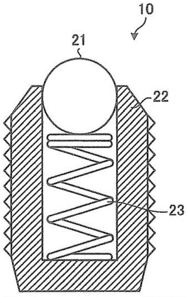
[0065] A roller plunger 31 as a vibration suppressing structure is arranged in the through hole 11 . The roller plunger 31 suppresses the vibration of the front bearing 8 caused by the driving of the rotating shaft 3 . The roller plunger 31 is screwed into the through hole 11 from the outer surface of the frame case 4 and inserted into the through hole 11 .

[0066] Figure 9 It is a figure which shows the cross-sectional structure of a roller plunger. The roller plunger 31 has a disk member 32 , a main body portion 33 , and a coil spring 34 . The main body portion ...

Example Embodiment

[0077] Embodiment 3.

[0078] Figure 10 It is a figure which shows the cross-sectional structure of the galvano scanner concerning Embodiment 3 of this invention. The galvano scanner 40 scans the object to be processed with the laser light from the laser light source. The same reference numerals are assigned to the same parts as those in Embodiment 1, and overlapping descriptions are appropriately omitted.

[0079] A spring structure 41 as a vibration suppressing structure is inserted into the through hole 11 . The spring structure 41 suppresses the vibration of the front bearing 8 caused by the driving of the rotating shaft 3 .

[0080] Figure 11 This is a side view showing an exploded spring structure. The spring structure 41 includes a spring member 42 , a positioning member 43 , and a main body portion 44 . The spring member 42 as an elastic member is an abutment member that abuts on the outer peripheral side surface of the front bearing 8 . The spring member 42 i...


PUM


Abstract

Provided is a galvano scanner comprising a rotating body that is provided with a rotation shaft (3) and is capable of rotating around the rotation shaft; a scan mirror (2) which is a mirror that deflects incident light and is connected to one end at the front side of the rotation shaft; a frame case (4) provided with an inner space in which the rotating body is rotated; a front-side bearing (8) which is a bearing provided at the front side end section of the inner space and rotatably supports the rotation shaft; and a ball plunger (10) which is a vibration suppression structure that suppresses vibrations of the front-side bearing caused by the driving of the rotation shaft. The vibration suppression structure has an abutting member that abuts an outer periphery side surface of the front-side bearing, and the abutting member is movable in accordance with displacement of the front-side bearing in an axial direction parallel to the rotation shaft.

Description

technical field [0001] The invention relates to an electric scanner and a laser processing device. Background technique [0002] A laser processing apparatus equipped with a galvano scanner is used, for example, for drilling holes in printed circuit boards and precision electronic components. With the development of finer electronic circuits and electronic components that become products, laser processing equipment is required to control the processing position with high precision. [0003] When the galvano scanner repeats the movement of the processing position at the same pitch, when the moving frequency of the processing position coincides with the natural vibration number of the rotating body, it may vibrate in the direction perpendicular to the surface of the mirror (plane tilt resonance) ). Since the traveling direction of the laser light from the reflection mirror changes due to the generation of plane tilt resonance, an error occurs in the position of the laser lig...

Claims


Application Information

Patent Timeline
IPC IPC(8): G02B26/10B23K26/08
CPCB23K26/08G02B26/10
Inventor 矛馆俊之高桥尚弘内山研吾高桥悌史
Owner MITSUBISHI ELECTRIC CORP
Why Eureka
Try Eureka