End effector mechanism of micro surgical instrument

An end-execution, micro-device technology, applied in the field of medical devices, can solve the problems of shortening the service life of the wire rope, reducing the placement space of the guide wheel, and the placement space of the guide wheel, etc., to increase the placement space, improve the reliability, and improve the processing technology. sexual effect

Active Publication Date: 2016-01-06
HARBIN SIZHERUI INTELLIGENT MEDICAL EQUIP CO LTD
View PDF5 Cites 17 Cited by
  • Summary
  • Abstract
  • Description
  • Claims
  • Application Information

AI Technical Summary

Problems solved by technology

Taking a three-degree-of-freedom end effector as an example, it is usually necessary to configure six wire ropes for driving, because the wire ropes must be carefully guided and arranged to pass through the end effector to maintain the tension of the wire ropes throughout the entire range of motion of the end effector and Minimize the interaction of one axis of rotation with the other, so the effective implementation of the end effector is complicated, due to the more wire ropes that need to be arranged, the existing technology has the problem of small space for the placement of the guide wheels, and the reduction of the space for the placement of the guide wheels , so that the diameter of the guide wheel is reduced, and the wrapping angle of the wire rope wound on the guide wheel is also correspondingly reduced, thereby shortening the service life of the wire rope and increasing the use cost

Method used


Image

  • End effector mechanism of micro surgical instrument
  • End effector mechanism of micro surgical instrument
  • End effector mechanism of micro surgical instrument

Examples


Embodiment

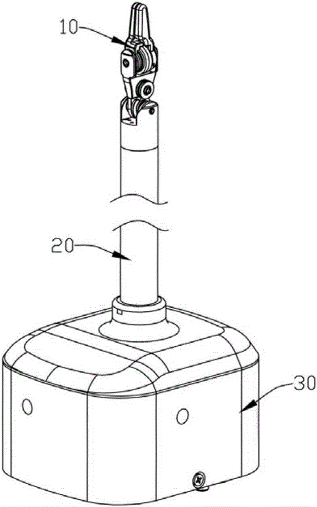
[0041] Embodiment: The embodiment of the present invention is illustrated by specific specific examples below. Those skilled in the art can easily understand other advantages and effects of the present invention from the contents disclosed in this description. The "top" mentioned in this embodiment, "Bottom" with figure 1 The directions of "top" and "bottom" are the same.

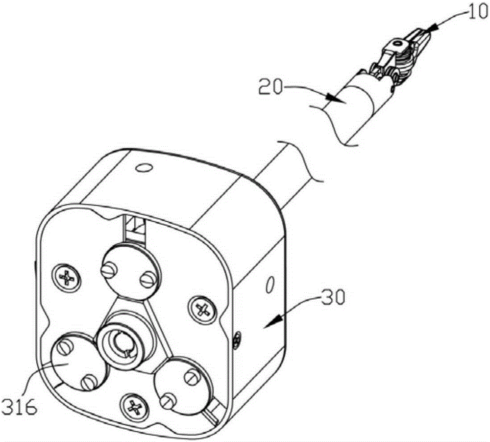
[0042] See figure 1 and figure 2 As shown, an end effector of a surgical micro-instrument includes: an interface board unit 30 connected to a driving device (not shown in the figure), a carbon fiber tube 20 connected to the interface board unit 30 and having a hollow structure, the The carbon fiber tube 20 is an elongated rod; the instrument clamp head unit 10 installed at the far end of the carbon fiber tube 20; Several wire ropes for controlling the action of the instrument forceps head unit 10 according to preset instructions.

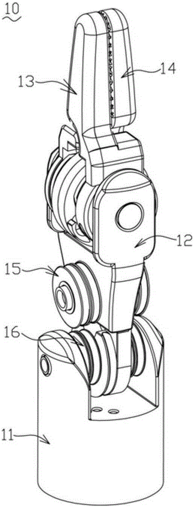
[0043] See Figure 3 to Figure 5 As shown, the instrument pliers unit ...


PUM


Abstract

The invention discloses an end effector mechanism for a micro surgical instrument. The end effector mechanism comprises an interface board unit connected with a driving device, a carbon fiber tube connected with the interface board unit and adopting a hollow structure, an instrument tong head unit mounted at the far-end part of the carbon fiber tube and a plurality of wire cables used for controlling the instrument tong head unit to act according to preset commands, wherein the instrument tong head unit comprises a support part, a left side tong head, a right side tong head, a guiding wheel set and a wrist part guiding wheel set, a pair of second connecting arms are symmetrically arranged at the top of the support part, the left side tong head and the right side tong head are hinged to the second connecting arms in a crossed manner, the guiding wheel set and the wrist part guiding wheel set are symmetrically mounted in the middle and at the lower part of the support part; and an eccentric balance wheel groove is formed in the side wall of the lower part of the support part. The end effector mechanism can effectively increase both the accommodating space and the diameters of the guiding wheels, so that the winding wrap angles of the wire cables on the guiding wheels are correspondingly increased, accordingly, the equivalent allowable strength of the wire cables is improved, and the service lives of both the wire cables and the micro instrument are prolonged.

Description

Technical field: [0001] The present invention relates to the technical field of medical equipment, and more specifically relates to an end effector of a micro-device. Background technique: [0002] Medical and surgical micro-instruments have the advantages of accurate positioning, stable operation, strong dexterity, large working range, and are not afraid of radiation and infection, and are widely used in various operations. The use of surgical micro-instruments helps to improve the accuracy of surgeons’ operations, solve the trembling, fatigue, and muscle and nerve feedback of surgeons’ hands, and enable doctors to perform operations in the most comfortable state. Patient pain is of great value, and its research has become a new field of medical device applications in recent years. [0003] Surgical microinstruments typically have an end effector in the form of a surgical tool, such as forceps, scissors, clips, etc., at one end of an elongated tube. The conventional motio...

Claims


Application Information

Patent Timeline
Patent Type & Authority Applications(China)
IPC IPC(8): A61B17/28
CPCA61B17/2812A61B2017/00367
Inventor 杜志江闫志远董为王吉
Owner HARBIN SIZHERUI INTELLIGENT MEDICAL EQUIP CO LTD
Why Eureka
Try Eureka