Channeling machine

A kind of technology of rolling groove machine and chassis, applied in the field of rolling groove machine, can solve the problems of inconvenient maintenance, complicated operation, needle drop of needle roller bearing, etc., and achieve the effect of convenient replacement

Active Publication Date: 2016-01-06
CEC JINJIANG INFO IND
View PDF6 Cites 2 Cited by
  • Summary
  • Abstract
  • Description
  • Claims
  • Application Information

AI Technical Summary

Problems solved by technology

See ZL03250037.8 "Steel Pipe Rolling Machine", the pressure roller used for rolling the groove of this type of rolling groove machine is installed in the middle of the pressure roller frame, and the pressure roller shaft passes through the pressure roller frame and the pressure roller, so when replacing the pressure roller The operation is complicated, and it is easy to cause the needle roller bearing in the middle of the pressure roller to drop the needle, which brings inconvenience to the user, short service life and inconvenient maintenance.

Method used


Image

  • Channeling machine
  • Channeling machine
  • Channeling machine

Examples


Embodiment Construction

[0020] The present invention will be further described below in conjunction with accompanying drawing, protection scope of the present invention is not limited to the following:

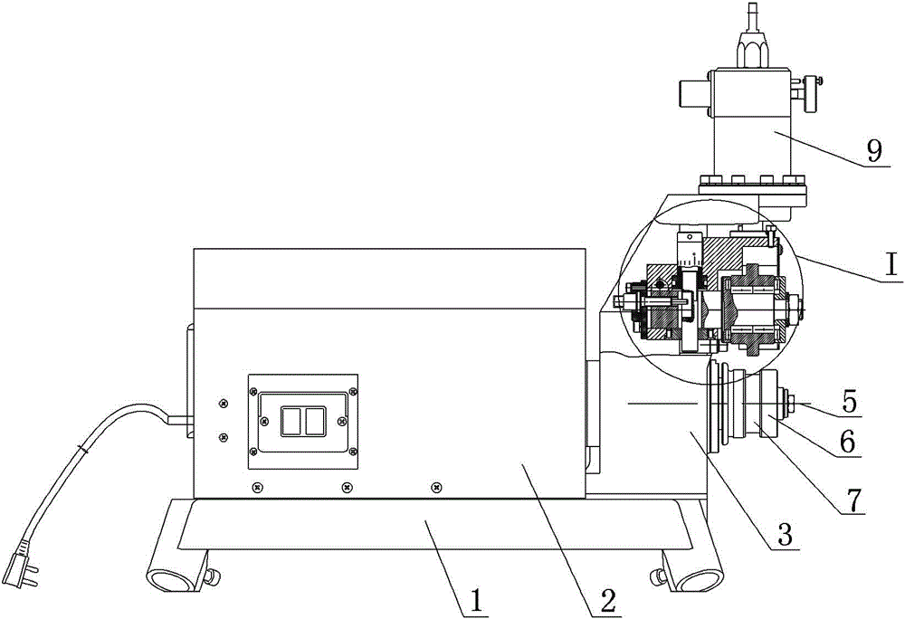
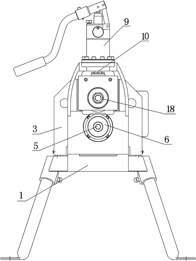
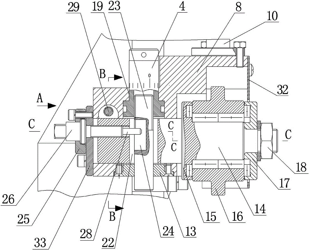
[0021] Such as Figure 1-9 Shown, a kind of grooving machine, it comprises platform 1, dial 4, main shaft 5, the cabinet 2 and frame 3 that are arranged on platform 1 and the motor and the reducer that are arranged in the cabinet 2, and motor is connected with reducer, The reducer is connected with the main shaft 5, the main shaft 5 is installed on the lower part of the frame 3, and the main shaft 5 is equipped with a knurled wheel 6 with a flange on the exposed side of the frame 3, the flange is used for positioning the steel pipe, and the knurled wheel 6 The middle part of the frame 3 is provided with an annular groove 7 for accommodating steel pipe deformed materials, the middle part of the frame 3 is provided with a square hole, and a slide seat 8 is installed in the square hole, and the top of t...


PUM


Abstract

The invention discloses a channeling machine. The channeling machine comprises a platform (1), a dial (4), a main shaft (5), a machine case (2) and a framework (3) arranged on the platform (1) and a motor and a speed reducer arranged in the machine case (2), wherein the motor is connected with the speed reducer; the main shaft (5) is provided with a knurl wheel (6) with a flange plate at an exposed side of the framework (3); rectangular guide rails (11) are respectively mounted at two sides of a right side plane of the framework (3) through bolts; the top end of a supporting rod is in threaded fit with the dial (4); the lower part of the supporting rod is matched with an end cover A (13) mounted on the bottom of the slide base (8), and extends out of the end cover A (13); the left end of a pressure wheel shaft (14) is provided with a threaded hole (27); a screw (26) is screwed into the threaded hole (27) in the tail part of the pressure wheel shaft (14); the right side of the screw (26) is provided with a cylinder (28); and the cylinder (28) extends into a long circular slot (24). The channeling machine has the beneficial effects of a long service life, convenience in replacing the pressure wheel, and simple operation.

Description

technical field [0001] The invention relates to the technical field of processing annular grooves on steel pipes, in particular to a rolling groove machine. Background technique [0002] At present, rolling grooving machines are widely used in construction and building fire protection, municipal water supply, and mine pipeline construction. Its function is to roll annular grooves on steel pipes, and use grooved pipe fittings to connect steel pipes. See ZL03250037.8 "Steel Pipe Rolling Machine", the pressure roller used for rolling the groove of this type of rolling groove machine is installed in the middle of the pressure roller frame, and the pressure roller shaft passes through the pressure roller frame and the pressure roller, so when replacing the pressure roller When pressing the wheel, the operation is complicated, and it is easy to cause the needle bearing in the middle of the pressure wheel to drop the needle, which brings inconvenience to the user, the service life ...

Claims


Application Information

Patent Timeline
Patent Type & Authority Applications(China)
IPC IPC(8): B21D17/04
Inventor 赫荣嘉钟传文
Owner CEC JINJIANG INFO IND
Why Eureka
Try Eureka