Online automatic U pipe inserting system

A pipe system and automatic technology, applied in metal processing, metal processing equipment, manufacturing tools, etc., can solve the problems of increased assembly time, low assembly efficiency, short U stuck, etc., to eliminate consistency problems and improve insertion U precision, the effect of avoiding insertion U misalignment

Active Publication Date: 2016-01-06
思睿智能医学科技(武汉)有限公司
View PDF5 Cites 10 Cited by
  • Summary
  • Abstract
  • Description
  • Claims
  • Application Information

AI Technical Summary

Problems solved by technology

This offline working method needs to use robots to take out and put the air conditioner condenser and evaporator back into the line body, which increases the assembly time and lowers the assembly efficiency. In addition, the air cylinder is used to directly clamp and position the air conditioner condenser and evaporator. In the actual working process, since the poses of the air conditioner condenser and evaporator on the line body cannot be exactly the same, the pose of the condenser when the robot grabs the air conditioner condenser and evaporator and places it in the assembly station cannot be completely the same. Similarly, this method of direct clamping and positioning using the cylinder tends to tilt the air conditioner condenser and evaporator, and the clamping accuracy is difficult to meet the working accuracy requirements of the subsequent short U tube insertion, while improving the accuracy of the short U tube insertion process. Short U tube consistency requirements
[0003] Especially for multiple jaws installed side by side in the sho

Method used


Image

  • Online automatic U pipe inserting system
  • Online automatic U pipe inserting system
  • Online automatic U pipe inserting system

Examples


Embodiment Construction

[0059] In order to make the objectives, technical solutions and advantages of the present invention clearer, the present invention will be described in further detail below in conjunction with the accompanying drawings and embodiments. It should be understood that the specific embodiments described here are only used to explain the present invention and are not intended to limit the invention.

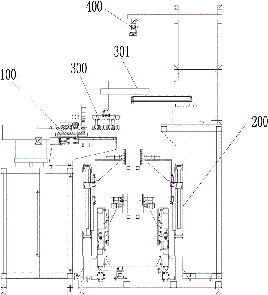
[0060] The invention provides an online automatic U tube insertion system, such as figure 1 As shown, it includes a screening and shaping mechanism 100 for screening and shaping the short U tube, an online positioning mechanism 200 for positioning and adjusting the air conditioner condenser, and an automatic mechanism for inserting the short U tube into the air conditioner condenser. The jaw floating mechanism 300, the initial position of the automatic jaw floating mechanism 300 corresponds to the stroke end of the screening and shaping mechanism 100, the end position of the automatic ...


PUM


Abstract

The invention discloses an online automatic U pipe inserting system. The online automatic U pipe inserting system comprises a screening and shaping mechanism used for screening and shaping short U pipes, an online positioning mechanism used for positioning and adjusting an air conditioner condenser, and an automatic clamping claw floating mechanism used for inserting the short U pipes into the air conditioner condenser. The initial position of the automatic clamping claw floating mechanism corresponds to the travel terminal of the screening and shaping mechanism, and the ending position of the automatic clamping claw floating mechanism corresponds to the travel terminal of the online positioning mechanism. According to the online automatic U pipe inserting system, the consistency of the short U pipes is improved through the screening and shaping mechanism, and automatic insertion of the short U pipes is facilitated; the online positioning mechanism is provided with an adjusting component and a horizontal limiting portion to carry out pose adjustment on workpieces before clamping and locating of the workpieces, so that the positions of the clamped workpieces meet the positioning requirement of U pipe inserting assembling, and the U pipe inserting precision is improved; the automatic clamping claw floating mechanism is used for automatically inserting the short U pipes into the air conditioner condenser.

Description

technical field [0001] The invention relates to the field of automatic assembly of short U pipes of air-conditioning condensing pipes, in particular to an online automatic U pipe insertion system. Background technique [0002] At present, the known automatic assembly of air conditioner condensers and evaporators is completed offline. The air conditioner condensers and evaporators are transported to designated locations through the line body, and then the air conditioner condensers and evaporators are grabbed from the line body by robots and put into assembly. In the assembly station, the cylinder is used for clamping and positioning, and the short U tube is inserted. After the short U tube is inserted, the robot is used to re-place the air conditioner condenser and evaporator on the line body and transport it to the next One station. This offline working method needs to use robots to take out and put the air conditioner condenser and evaporator back into the line body, whic...

Claims


Application Information

Patent Timeline
IPC IPC(8): B23P19/00
CPCB23P19/00
Inventor 沈翔
Owner 思睿智能医学科技(武汉)有限公司
Why Eureka
Try Eureka