
Automobile flywheel drilling device with mechanical automatic positioning function

An automatic positioning and drilling device technology, applied in positioning devices, boring/drilling, drilling/drilling equipment, etc., can solve the problems of water waste, no filter, anti-blocking and cleaning, and unfavorable use by staff. , to achieve the effect of ensuring normal use, saving water resources and improving efficiency

Pending Publication Date: 2020-09-04
广西金锋汽车零部件制造有限公司
View PDF0 Cites 2 Cited by
  • Summary
  • Abstract
  • Description
  • Claims
  • Application Information

AI Technical Summary

Problems solved by technology

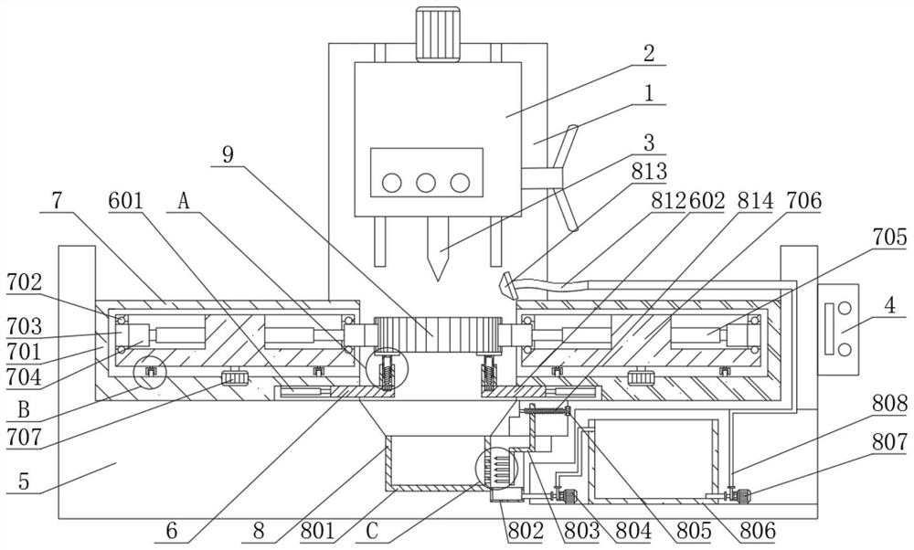
[0003] The flywheel needs to be drilled on the inner side of the flywheel through the drilling device during the production process. The general drilling device does not have the function of automatically clamping and positioning the flywheel. Manual clamping is required or the staff fixes the flywheel by hand during the drilling process. , which is not conducive to the use of staff, and the general drilling device does not have the function of spraying water to cool the drill bit, or the existing water spray cooling function cannot recycle water, resulting in a waste of water resources The filter screen has the function of anti-blocking and cleaning, therefore, a kind of automobile flywheel drilling device with mechanical automatic positioning function is proposed in view of the above problems

Method used


Image

  • Automobile flywheel drilling device with mechanical automatic positioning function
  • Automobile flywheel drilling device with mechanical automatic positioning function
  • Automobile flywheel drilling device with mechanical automatic positioning function

Examples


Embodiment Construction

[0027] see Figure 1-7 , the present invention provides a technical solution:

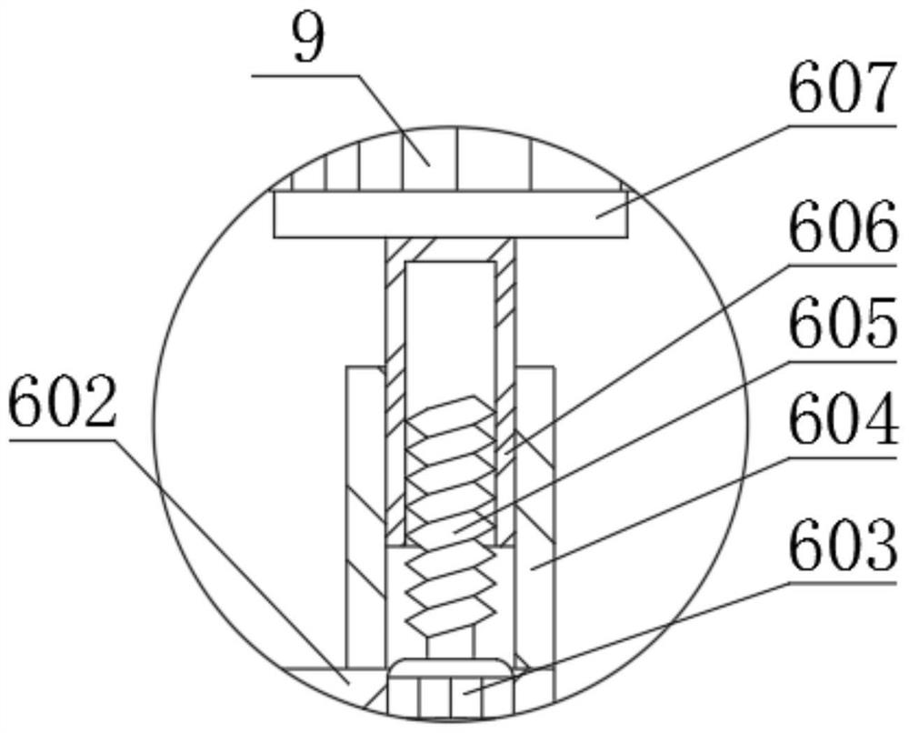
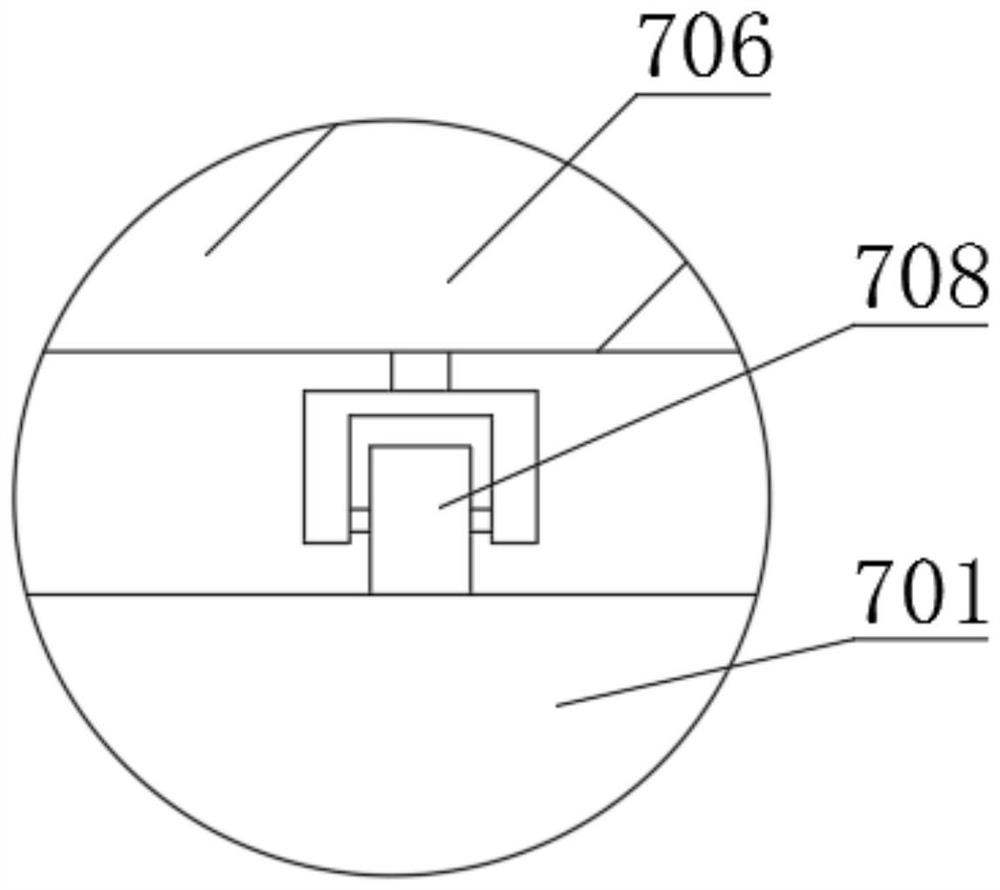
[0028] An automobile flywheel drilling device with mechanical automatic positioning function, comprising a base 5, a fixed base 1 is fixedly connected to the rear side of the top of the base 5, the front end of the fixed base 1 is fixedly connected to a numerical control case 2, and the inner side of the numerical control case 2 is fixedly connected There is a drill bit 3, a controller 4 is fixedly connected to the right end of the base 5, a positioning device 7 is fixedly connected to the top of the base 5, a support device 6 is fixedly connected to the bottom end of the positioning device 7, and a cooling device 8 is fixedly connected to the inner side of the base 5, The inner side of the positioning device 7 is provided with a flywheel 9, and the positioning device 7 includes a positioning plate 701, a ball 702, a positioning block 703, a connecting block 704, a second electric telescopic rod 70...


PUM


Abstract

The invention relates to the technical field of automobile flywheel machining, in particular to an automobile flywheel drilling device with a mechanical automatic positioning function. The device comprises a base, the top end of the base is fixedly connected with positioning devices, and the positioning devices comprise positioning plates, balls, positioning blocks, connection blocks, second electric telescopic rods, disks, second motors and wheels. The positioning plates are fixedly connected to the top end of the base, the second motors are fixedly connected with the inner sides of the top ends of the positioning plates, and the disks are fixedly connected with the tail ends of main shafts of the second motors. In the device, through the arrangement of the positioning plates, the balls,the positioning blocks, the connection blocks, the disks, the second motors and the wheels, the positioning blocks are driven by the second electric telescopic rods to quickly clamp and position a flywheel, the flywheel does not need to be clamped and fixed manually, and therefore the clamping and positioning efficiency is improved. Meanwhile, flywheels in different specifications can be clamped and positioned through the positioning blocks in different specifications, so that the device is more automatic.

Description

technical field [0001] The invention relates to the technical field of automobile flywheel processing, in particular to an automobile flywheel drilling device with a mechanical automatic positioning function. Background technique [0002] The flywheel is a wheel-shaped accumulator with a large moment of inertia installed on the rotary shaft of the machine. When the machine speed increases, the kinetic energy of the flywheel increases to store energy; when the machine speed decreases, the kinetic energy of the flywheel decreases and the energy is stored. Unleashed, the flywheel can be used to reduce speed fluctuations during mechanical operation. [0003] The flywheel needs to be drilled on the inner side of the flywheel through the drilling device during the production process. The general drilling device does not have the function of automatically clamping and positioning the flywheel. Manual clamping is required or the staff fixes the flywheel by hand during the drilling p...

Claims


Application Information

Patent Timeline
Patent Type & Authority Applications(China)
IPC IPC(8): B23B41/00B23B47/00B23Q3/06B23Q11/10
CPCB23B41/00B23B47/00B23Q3/06B23Q3/062B23Q11/10B23Q11/1069
Inventor 陈木水陈志超凌雪萍陈志开张明乾庞勋凌富浇陈森黎红梅周培峰龙文耀
Owner 广西金锋汽车零部件制造有限公司
Learn More