

Shock-absorbing and buffering assembly of bridge and monitoring system
A monitoring system and bridge technology, applied in bridge parts, bridges, bridge materials, etc., can solve problems such as easy leakage, large property loss, and leakage, and achieve the effect of ensuring balance, avoiding tilt, and ensuring stability
- Summary
- Abstract
- Description
- Claims
- Application Information
AI Technical Summary
Problems solved by technology
Method used
Image

Examples
Embodiment 1
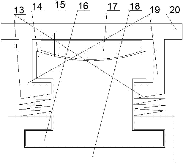
[0036] A bridge shock absorbing and buffering assembly and monitoring system, comprising an L-shaped slide rail 19 arranged at the bottom of a bridge 20, an I-shaped steel 14 located in the L-shaped slide rail, an arc surface arranged on the I-shaped steel, an arc surface arranged on the arc The slide block with rubber and it on the shape surface 15, the base that is sleeved under the I-beam, the track mechanism that is arranged on the bottom surface of the bridge, the detection mechanism that is arranged on the track mechanism for detecting the actual situation of the bridge bottom surface, the L Connected by spring 13 between the shaped slide rail and the base;
[0037] The lower plate 16 of the I-shaped steel is located in the slideway of the base 18 .
[0038] The two L-shaped slide rails are covered with gaps on the I-shaped steel.
[0039] The slider is made of elastic material, the elastic force of the spring is greater than the self-weight of the bridge plate, and the...
Embodiment 2
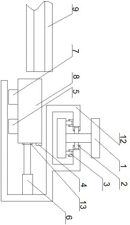
[0053] The traveling wheel set comprises a horizontal traveling wheel 3 and a vertical traveling wheel 2 arranged on the I-shaped steel track;
[0054] The auxiliary traveling mechanism includes an auxiliary traveling seat 8, which is arranged on the auxiliary traveling seat 8 for driving the auxiliary traveling wheel set;
[0055] The main track adopted in this embodiment is an I-steel track arranged along one side of the bottom surface of the bridge, and the auxiliary track is an auxiliary I-steel track arranged on the bridge hole surface of the bottom surface of the bridge and perpendicular to the I-steel track; To ensure the stability of the structure and prevent the device from falling due to wind, the walking mechanism adopted includes a walking seat, a walking wheel set arranged on the upper part of the walking seat, and a walking wheel set arranged in the walking seat. Auxiliary walking mechanism, the mechanical arm that is arranged on the walking seat and cooperates w...
Embodiment 3
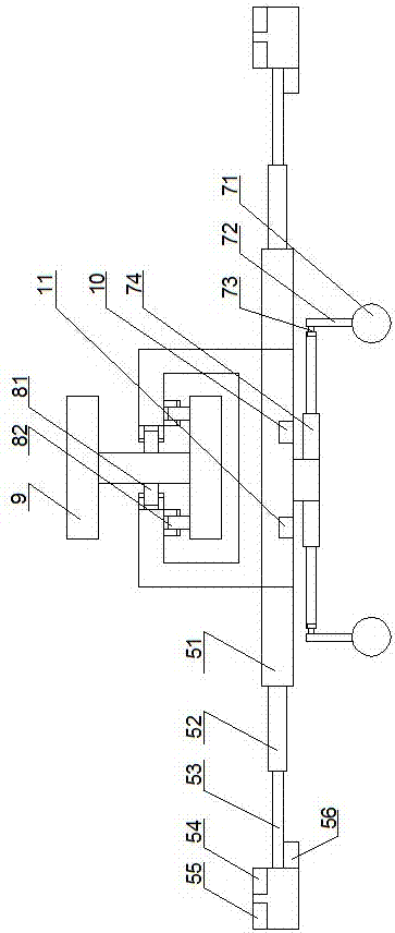
[0057] The vertical height of the auxiliary I-shaped steel guide rail is lower than that of the main I-shaped steel guide rail.
[0058] In this embodiment, the balance module is adopted to include a MEMS gyroscope and a MEMS accelerometer arranged on the auxiliary walking seat, and the auxiliary telescopic rods arranged on both sides of the auxiliary walking seat are arranged at the ends of the auxiliary telescopic rods through adjustment. The balance pole set by the motor, the balance ball set at the lower end of the balance pole; the data monitoring is realized through the gyroscope and the accelerometer, and then fed back to the control chip on the balance module, which realizes dynamic balance, and the telescopic module adopted It includes a first-stage telescopic rod, a second-stage telescopic rod arranged on the first-stage telescopic rod, and a third-stage telescopic rod arranged on the second-stage telescopic rod; through hierarchical expansion and contraction, it is ens...
PUM
 Abstract
Description
Claims
Application Information