
A high-frequency ultrasonic polishing device and method using a matching layer composite piezoelectric vibrator

A piezoelectric vibrator and matching layer technology, which is applied in the field of high-frequency ultrasonic composite polishing devices, can solve the problems of difficult frequency increase, limited ultrasonic energy, difficulty in efficient use of ultrasonic vibration and global flattening of workpieces, etc., to achieve flexible attachment and structure simple effect

Inactive Publication Date: 2017-11-21
LIAONING UNIVERSITY OF TECHNOLOGY
View PDF5 Cites 0 Cited by
  • Summary
  • Abstract
  • Description
  • Claims
  • Application Information

AI Technical Summary

Problems solved by technology

At present, the material removal unit in the polishing process has been at the nanometer or even sub-nanometer level. At this processing scale, it is difficult to achieve high-efficiency ultrasonic vibration due to the limitation of the vibrator structure and vibration mode in low-frequency ultrasonic polishing of tens of kilohertz. Utilization and global planarization of artifacts
[0003] When the amplitude of the ultrasonic machining tool is constant, the higher the frequency, the greater the ultrasonic energy. The traditional ultrasonic vibration polishing tool relies on the overall modal analysis and design of the vibrating elastic body, which is limited by the structure of the vibrator. , the frequency is not easy to increase, generally limited to the low ultrasonic frequency band of tens of kilohertz to hundreds of kilohertz, so the energy of ultrasonic action is limited

Method used


Image

  • A high-frequency ultrasonic polishing device and method using a matching layer composite piezoelectric vibrator
  • A high-frequency ultrasonic polishing device and method using a matching layer composite piezoelectric vibrator

Examples


Embodiment Construction

[0015] The present invention will be described in further detail below in conjunction with the embodiments shown in the accompanying drawings.

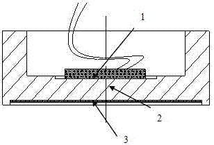
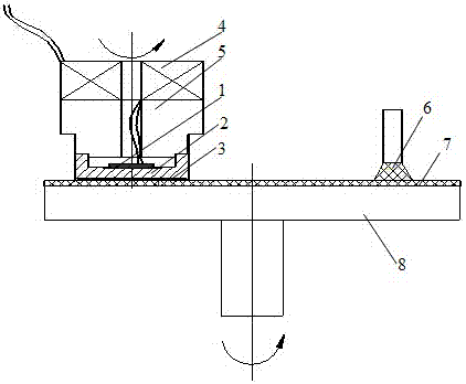
[0016] The labels in the figure are: 1. Piezoelectric ceramics; 2. Matching layer I; 3. Matching layer II (part to be polished); 4. Brush slip ring; 5. Weight; 6. Polishing liquid; 7. Polishing pad; 8. Polishing workbench;

[0017] The shaft hole of the brush slip ring 4 is connected with the weight 5 through clearance fit, and the leading wire of the slip ring 4 is connected to the piezoelectric ceramic sheet 1 through the middle through hole of the weight 5, and the piezoelectric ceramic sheet 1 is made of epoxy resin The adhesive is pasted on the matching layer I, the matching layer II is adsorbed on the matching layer I by the water of the polishing piece, and the polishing pad 7 is pasted on the polishing workbench 8 .

[0018] The traditional low-frequency power ultrasonic vibrator has a complex structure, and is limited by the...


PUM


Abstract

The invention provides a high-frequency ultrasonic polishing device and method utilizing matching layer composite piezoelectric vibrators, and relates to an ultrasonic compound polishing device and method. The device is composed of an ultrasonic vibration adding system and a traditional chemical and mechanical polishing system. The ultrasonic vibration adding system comprises piezoelectric ceramic, a matching layer I, a polished part and corresponding electrical input equipment. The method comprises the steps that high-frequency ultrasonic waves generated by the piezoelectric vibrators must penetrate through double matching layers including the polished part to act on a polishing interface, and materials and the thickness of the matching layer I pasted to the piezoelectric ceramic are adjusted and selected according to changes of materials and the thickness of the polished part; the frequency of the high-frequency ultrasonic waves is within the high-frequency ultrasonic field ranging from hundreds of kilohertz to several megahertz; and a piezoelectric ceramic sheet is of a high-power radiation type and works in a thickness resonance vibration mode of the piezoelectric ceramic sheet. By means of the device and method, the process of ultrasonic-assisted chemical and mechanical finishing polishing or rough polishing on different materials and different regions can be achieved.

Description

technical field [0001] The invention relates to an ultrasonic composite polishing device and method, in particular to a high-frequency ultrasonic composite polishing device and method for hundreds of kilohertz to several megahertz matching layer structure transducers. Background technique [0002] The traditional ultrasonic-assisted processing technology uses the vibration shock, abrasive shock and cavitation generated by ultrasonic frequency vibration of tens of kilohertz to remove material. The application of ultrasonic vibration to the process of mechanical polishing or chemical mechanical polishing can significantly promote the reduction of the surface roughness of the polished piece and the improvement of polishing efficiency. At present, the material removal unit in the polishing process has been at the nanometer or even sub-nanometer level. At this processing scale, it is difficult to achieve high-efficiency ultrasonic vibration due to the limitation of the vibrator s...

Claims


Application Information

Patent Timeline
Patent Type & Authority Patents(China)
IPC IPC(8): B24B1/04
CPCB24B1/04
Inventor 何勍翟科
Owner LIAONING UNIVERSITY OF TECHNOLOGY
Learn More