
Compression bottle cap machine mold cooling mechanism

A mold cooling and bottle cap machine technology, applied in the field of plastic machinery, can solve the problems of many watermarks, uneven cooling of bottle caps, easy heating of molds, etc.

Active Publication Date: 2018-08-03
TAIZHOU HUANGYAN YIJING PLASTIC & MOLD
View PDF7 Cites 0 Cited by
  • Summary
  • Abstract
  • Description
  • Claims
  • Application Information

AI Technical Summary

Problems solved by technology

However, the current bottle cap molds all adopt bottom cooling and rotating cavity cooling methods, which have disadvantages such as uneven cooling of the bottle cap, unsmooth cooling water circulation, small cooling area, and poor effect, which lead to the mold being prone to heat, long service life, and the product There are many watermarks on the appearance, making the product surface unattractive

Method used


Image

  • Compression bottle cap machine mold cooling mechanism
  • Compression bottle cap machine mold cooling mechanism
  • Compression bottle cap machine mold cooling mechanism

Examples


Embodiment Construction

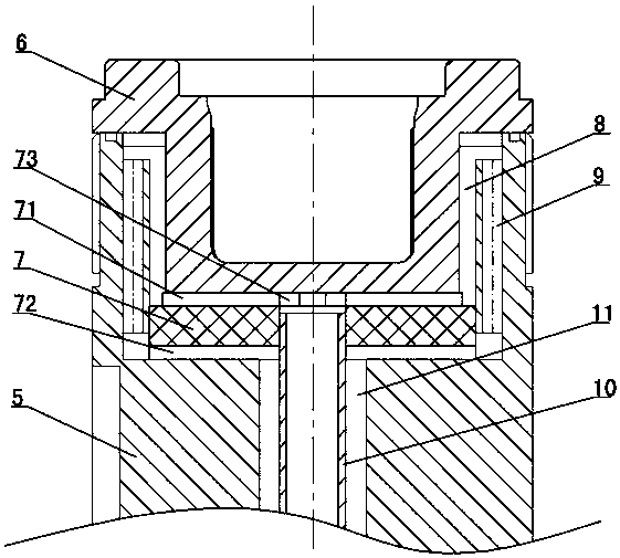
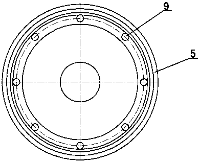
[0013] The invention relates to a mold cooling mechanism of a compression molding bottle cap machine, such as figure 1 — Image 6 Shown, comprise the mold of compression molding bottle cap machine, described mold comprises upper mold and lower mold, and described upper mold comprises upper mold guide rod 1, and the head of upper mold guide rod is provided with upper mold core 2, and upper mold The upper mold cooling water hole 3 is formed in the guide rod, and the upper mold cooling water joint 4 is installed at the tail of the upper mold guide rod, and the lower mold includes the lower mold guide rod 5, and the lower mold cavity 6 is set on the head of the lower mold guide rod , the water distribution gasket 7 is set between the bottom of the lower mold cavity 6 and the lower mold guide rod 5, the top surface of the water distribution gasket 7 is provided with an upper cold water tank 71, and the bottom surface of the water distribution gasket 7 is provided with a lower cold ...


PUM


Abstract

The mold cooling mechanism of the compression molding bottle cap machine includes an upper mold guide rod and a lower mold guide rod. The head of the upper mold guide rod is provided with an upper mold core, and the head of the lower mold guide rod is provided with a lower mold cavity. A water diversion gasket is arranged between the guide rods of the lower mold, and an upper cold water tank, a lower cold water groove and a through hole are arranged on the water diverter gasket, and the gap between the outer wall around the lower mold cavity and the lower mold guide rod forms a cooling groove , the upper cold water tank communicates with the cooling groove, the lower mold guide rod is shaped with a return hole, the cooling groove communicates with the return water hole, the return water hole communicates with the lower cold water tank, and a stainless steel pipe is installed in the lower die guide rod, The gap between the stainless steel pipe and the guide rod of the lower die forms a return water groove, and the lower cold water tank communicates with the return water groove. The water port is connected to the stainless steel pipe, the stainless steel pipe is inserted into the through hole to communicate with the upper cold water tank, and the water inlet and the water return port are connected to the cooling water machine.

Description

technical field [0001] The invention relates to a bottle cap machine, in particular to a mold cooling mechanism of a compression molding bottle cap machine, which belongs to the field of plastic machinery. Background technique [0002] The bottle caps of plastic bottles (such as mineral water bottles, beverage bottles and oil bottles, etc.) are generally formed by compression molding of the bottle cap machine. Cavity) for cooling to enhance product shaping and reduce mold temperature. However, the current bottle cap molds all adopt bottom cooling and rotating cavity cooling methods, which have disadvantages such as uneven cooling of the bottle cap, unsmooth cooling water circulation, small cooling area, poor effect, etc., resulting in easy heating of the mold and long service life. There are many watermarks on the appearance, which makes the product surface unattractive. Contents of the invention [0003] The purpose of the present invention is to overcome the shortcomin...

Claims


Application Information

Patent Timeline
Patent Type & Authority Patents(China)
IPC IPC(8): B29C43/52B29C43/36
Inventor 黄海燕
Owner TAIZHOU HUANGYAN YIJING PLASTIC & MOLD
Learn More