Coaxial double-rotor-wing system of aircraft

A coaxial dual-rotor, aircraft technology, applied in the field of aviation aircraft, can solve the problems of low helicopter flight speed, increase the backward propeller, increase the angle of attack of the blade, etc., to avoid large fluctuations, reduce invalid consumption, and reduce aerodynamics The effect of resistance

Inactive Publication Date: 2016-01-06
DEA GENERAL AVIATION HLDG CO LTD
View PDF5 Cites 20 Cited by
  • Summary
  • Abstract
  • Description
  • Claims
  • Application Information

AI Technical Summary

Problems solved by technology

increasing the blade angle of attack can cause an increase in blade profile drag, resulting in ineffective consumption of energy that would otherwise be used to rotate the rotor
However, as the flight speed increases, the reverse turbulence area increases, and the angle of attack of the backward blade must be increased until the maximum value, resulting in blade airflow separation and loss of lift characteristics. These factors limit the level flight speed of the helicopter
[0006] (2) At the same time, under the condition of satisfying the lift compensation condition of the rotor disk, with the increase of the flying speed of the helicopter, the aerodynamic limitation appears when the airflow separation occurs on the blades on the one hand, and on the other hand, when it reaches the air supersonic turbulence zone This is the reason why the helicopter flies at a relatively low speed
Furthermore, when using the forward-advancing blade concept, one autotilt cannot simultaneously (differentially) manipulate the angle of attack of the forward-advanced and aft-advanced blades of the upper and lower rotors

Method used


Image

  • Coaxial double-rotor-wing system of aircraft
  • Coaxial double-rotor-wing system of aircraft
  • Coaxial double-rotor-wing system of aircraft

Examples


Embodiment Construction

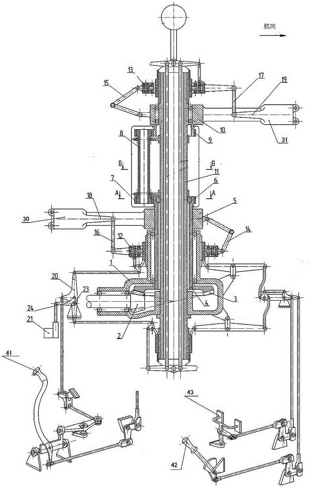
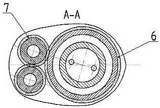
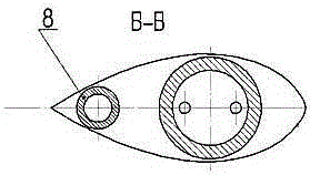
[0029] like figure 1 , 2 , 3, the coaxial dual-rotor system of the present invention mainly includes a speed reducer 1, a lower rotor shaft 4, a lower rotor hub 5, a lower rotor, an upper rotor shaft 11, an upper rotor hub 10, an upper rotor and a control link.

[0030] In the present invention, the upper and lower rotors adopt rigid coaxial rotors with only axial hinges, which are used to control the upper and lower rotors. . The differential pitch control mechanism also includes the cyclic pitch control mechanism and the differential cyclic pitch control mechanism. The functions of each control mechanism in the control link are:

[0031] The collective distance control mechanism is used to control the upper automatic tilter 13 and the lower automatic tilter 12 to move up and down in the vertical direction (the vertical direction here refers to the direction perpendicular to the horizontal plane), and then change the collective distance to realize the helicopter take-off, de...


PUM


Abstract

The invention relates to a coaxial double-rotor-wing system of an aircraft. The coaxial double-rotor-wing system comprises a speed reducer, a lower rotor wing shaft, a lower rotor wing hub, a lower rotor wing, an upper rotor wing, an upper rotor wing shaft, an upper rotor wing hub, an upper rotor wing and a control link or controlling the upper rotor wing and the lower rotor wing and is characterized in that the upper rotor wing and the lower rotor wing are rigid coaxial rotor wings only provided with an axial hinge, a pull rod direct-connection structure between the upper automatic inclinator and the lower automatic inclinator of the control link is omitted, and the control link further comprises a cyclic pitch control mechanism and a differential cyclic pitch control mechanism. The coaxial double-rotor-wing system has the advantages that lift force compensation of the rotor wings is omitted by utilizing the rigid coaxial rotor wings; further aerodynamic limiting caused by air flow separation and air supersonic turbulent flows is avoided under the situation that the condition of lift force compensation is not met; a retreating propeller pitch is decreased by adding the differential cyclic pitch control mechanism, accordingly the aerodynamic resistance of the retreating positions of rotor wing blades can be reduced, ineffective consumption is reduced, and the flat flight speed is improved based on the same output power.

Description

technical field [0001] The invention relates to an aviation vehicle, in particular to a coaxial dual-rotor system of the aircraft. Background technique [0002] As we all know, the coaxial dual-rotor system is used to generate lift and maneuver the helicopter. This system has been applied to Ka-26, Ka-32 and other types of helicopters. The characteristics of this system are listed in the above-mentioned Kamov company. A detailed description has been made in the technical manual of the model helicopter, so I won't make a larger introduction here. [0003] Among the currently known schemes, the coaxial dual-rotor system of the card-32 helicopter is the closest to the present invention. The structure of the coaxial dual-rotor system of the card-32 helicopter mainly includes: a reducer and 2 shafts rotating in opposite directions, and the upper The hubs of the lower and lower rotors are respectively fixed on two shafts rotating in opposite directions, and the upper and lower ro...

Claims


Application Information

Patent Timeline
Patent Type & Authority Applications(China)
IPC IPC(8): B64C27/10B64C27/80
Inventor 刘宏伟程明哲韩杰
Owner DEA GENERAL AVIATION HLDG CO LTD
Why Eureka
Try Eureka